Did you measure and select matching surface mount resistors?
Yes, I hand matched them all.
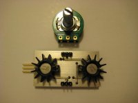
I etched some new boards that have a jumper to put the buffer outside the feedback loop. It will be interesting to hear what kind of difference it makes. I also made a current-feedback version minus the buffers based on the LME49713. It sounds really amazing. Offset on that board is ~9mV per channel.
I wasn't thinking when I posted last night. I forgot there is that servo there. I'd have though that should neutralise the offset?
It it too difficult to swap the 49720 chips over and see if the offset changes with them? Or the buffers?
Where did you find a suggested schematic and components / values for that chip? I looked this week but didn't find any. Regarding the data sheet, I guess they sacked the applications engineers before they did any. It's a bit sparse! It does say the max drive is 100mA. Would that be marginal for head phones?
Post no. 6: http://www.diyaudio.com/forums/solid-state/132471-national-opamp-inflation.html#post1707305
Last edited:
I wasn't thinking when I posted last night. I forgot there is that servo there. I'd have though that should neutralise the offset?
I'm not well versed in this stuff, but it seems like it only nulls input offset and not the natural output offset of the IC.
It it too difficult to swap the 49720 chips over and see if the offset changes with them? Or the buffers?
It's not high enough for me to worry about it. Lower is always better, but 20mV is the upper limit of acceptable. I will be putting together another one soon anyway, so I we'll see how the offset is on that one.
Where did you find a suggested schematic and components / values for that chip? I looked this week but didn't find any. Regarding the data sheet, I guess they sacked the applications engineers before they did any. It's a bit sparse! It does say the max drive is 100mA. Would that be marginal for head phones?
The headphone amp circuit with servo is in the LME49600 datasheet.
The LME49713 datasheet is pretty sparse, but all the relevant info is there. The 100mA output current is plenty for most headphones, especially high impedance ones. I built the board for a friend who has 300-Ohm HD650's, but it drives my 32-Ohm cans just fine.
Any chance you'd be willing to share your PCB file?
For which board?
I don't have any PCB files though; just unlabeled etch patterns in PDF format. You would have to "reverse engineer" what goes where and which pads were used for ground plane wire vias and such.
Sorry I meant where did you find a suggested schematic and components values for the LME49713?
The low cost headphones (£5) which I bought 6 years ago for listening for detonation in the car engine are not too bad really for vocals in news and youtube clips, etc, apart from the lack of bass, treble, dynamics, are about 34 Ohms. So should be OK then.") I'm probably going to buy a pair of HD201's as the next step to see how they are better.
I'm probably going to buy a pair of HD201's as the next step to see how they are better.
I've not used headphones before. Have a very decent home theatre set up but the 'cans' have been proving very practical compared to powering up the whole system just to watch some small internet videos. Though currently the home theatre is better in all the above mentioned way plus has surround, which the cans will not do, however good they are. Unless they're Zalman ones, but apparently they don't do bass, with a cut off stated at only 50Hz.
Thanks.
The low cost headphones (£5) which I bought 6 years ago for listening for detonation in the car engine are not too bad really for vocals in news and youtube clips, etc, apart from the lack of bass, treble, dynamics, are about 34 Ohms. So should be OK then.
I'm probably going to buy a pair of HD201's as the next step to see how they are better.I've not used headphones before. Have a very decent home theatre set up but the 'cans' have been proving very practical compared to powering up the whole system just to watch some small internet videos. Though currently the home theatre is better in all the above mentioned way plus has surround, which the cans will not do, however good they are. Unless they're Zalman ones, but apparently they don't do bass, with a cut off stated at only 50Hz.
Thanks.
Last edited:
Sorry I meant where did you find a suggested schematic and components values for the LME49713?
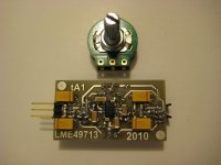
Oh, I meant that the circuit is the exact same one found in the LME49600 datasheet minus the buffers.
The only real difference besides the missing buffers is the feedback resistor which I changed to 2k, and an input RC filter of 500R/220pF. I changed Rf for two reasons; to raise the gain for my application (5x) and to lower the bandwidth of the circuit (CF op-amps BW controlled by Rf value).
Here is my LME49713 board.....
Attachments
Hi, could someone please post schematic and parts details so amateurs like me can understand? thank you.
The schematic is on page 11 of the LME49600 datasheet......
http://www.national.com/ds/LM/LME49600.pdf
Hi,
It looks like you're using a DC servo on the LME49713's. Any reason why? The offset voltage of the LME49713 is specified to be less than 1.0 mV. I would think you could do without the servo.
~Tom
Only becuase it's a DC coupled design. If I'm using a source with any DC offset it will get amplifed by the 5x gain.
Only becuase it's a DC coupled design. If I'm using a source with any DC offset it will get amplifed by the 5x gain.
Good point. Thanks for clarifying.
~Tom
Only becuase it's a DC coupled design. If I'm using a source with any DC offset it will get amplifed by the 5x gain.
possible to put in a cap at the input, and a cap at the output to block the dc then?
possible to put in a cap at the input, and a cap at the output to block the dc then?
No thanks.
I just got some feedback from the person who I built the LME49713 amp for. He said he likes the previous amp I built him better (LME49710HA/LME49600).
He said the 49710/49600 amp has much better bass and midrange; where the 49713 sounds thin and clinical.
His cans are HD650's.
He said the 49710/49600 amp has much better bass and midrange; where the 49713 sounds thin and clinical.
His cans are HD650's.
Did both old and new have the same power supply?
Yes, they were identical.
He kind of reversed his initial criticisms though and decided to keep the LME49713 amp.
I didn't have them both in my possession at the same time so I can give an accurate description of any differences between the two. I liked them both, but I spent a lot of time building them so I guess I'm biased.
Hi there
I was wondering if there was any further feedback on the choice between the two.
Thanks.
Istarted using headphones quite a lot a few weeks ago. I found in the data sheet that the 49720HA can drive about 26mA into a 600 Ohm load, I guess he 10HA can also. My HD600's are 300 Ohms and the sound card has a 200 Ohm output resistor, Sennheiser say the HD600 only needs 1mW so I tried them in with the soundcard and it's quite good. Better than the micro USB converter / DAC / driver I was using.
So now I'm thinking about converting the sound card to push pull output (what the head-fi people call 'Balanced') as I read many favourable reports of this method beating 'single ended' output.
I wonder whether to add another 49710HA's to each channel. Or that and follow them each with a 49600HA or use two 49713HA per channel.
Last edited:
I don't think trying to cobble together a balanced output stage on the soundcard is a very good idea.
I would use the output stage of the soundcard to feed a good stepped attenuator and then put your balanced headphone amp circuit after that.
As to which chip is better sonically; I don't think anyone can tell you which one you will personally think sounds better. The 49713 does have the advantage of 3x the output current of the 49710, but it is current-feedback and requires special attention to circuit design.
- Status
- This old topic is closed. If you want to reopen this topic, contact a moderator using the "Report Post" button.
- Home
- Amplifiers
- Chip Amps
- Lme49600 headphone amp