Hmmm, I'm curious now to know how much, if any, oscillation is taking place with my board.
Anyone here interested in putting in under their scope? You can keep it when your done.
jcx?
What an offer. I'll test it for oscillation if you like (and it is still available). I'll send you a PM with my address.
Hmmm, I'm curious now to know how much, if any, oscillation is taking place with my board.
jcx?
I was wondering if you tied the BW pin to V- or let it float?
I was wondering if you tied the BW pin to V- or let it float?
Dear,
I would not let if float. With tying the BW pin to V- you put the buffer in Class A, a feature u don't want to skip. Besides, even if you limit the bandwidth of the buffer, the driver still has a high open-loop bandwidth. Even though you don't find oscillations, the total bandwidth for audio is way to high, So I would use at least a 47p from driver output to negative input as indicated in my schematic anyway. Even with 100p you still have a band-with till over 200Khz.
With kind regards,
Bas
What an offer. I'll test it for oscillation if you like (and it is still available). I'll send you a PM with my address.
PM received.
If you could possibly get some scope shots of the output and post them here that would be great.
Like I mentioned, the board works perfectly and sounds great. I'm just curious now to see if there is any nasty stuff going on that, if there is, I can obviously live with.
The 47pf cap suggested by Sebastian is probably a good idea anyway and something I will include if I build another board.
I was wondering if you tied the BW pin to V- or let it float?
It's tied to V- just like the schematic.
PM received.
If you could possibly get some scope shots of the output and post them here that would be great.
No problem. They will be genuine scope shots, i.e. digital photos of the phosphorous screen.
I've been playing with speakers for the last couple of years; but about 10 years ago I took the moniker "benchtester" when I was designing high bandwidth power amps. I get a kick out of seeing how fast I can tune an amp before oscillations become a problem (fail to decay).
How many flames and smoke you went through?

How many flames and smoke you went through?
Not a lot. The secret is to start with high impedance loads ~100 ohms, then low impedance but low input, and finally full power after you are confident in the circuit.
I only remember two war stories: first was when a carbon resistor flamed due to oscillations. It looked just like a burning match inside my amp. I threw out every carbon resistor in my inventory after that, and I only use flameproof metal film resistors now. BTW my local DIY event is called "Burning Amp"; I qualify
.Second was not an oscillation issue. I moved a power op amp (PA05) circuit board with power on it and apparently shorted something. It fried a $300 multichip module. No way around it: that hurt!
PM received.
If you could possibly get some scope shots of the output and post them here that would be great.
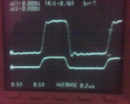
Sickness and work have been getting in the way, but I did complete one simple test which looks pretty good.
The lower trace is a 1 MHz square wave in (~.5 volts in p-p) and the upper trace is the output (~1.5 volts out p-p) without any load besides the oscilloscope.
One can see some ringing at 10 MHz, but it decays nicely. I think this circuit is pretty good just the way it is. I will try to follow-up with more tests such as capacitive loading, but it may be a week or two before I get some more hobby time.
Attachments
Sickness and work have been getting in the way, but I did complete one simple test which looks pretty good.
The lower trace is a 1 MHz square wave in (~.5 volts in p-p) and the upper trace is the output (~1.5 volts out p-p) without any load besides the oscilloscope.
One can see some ringing at 10 MHz, but it decays nicely. I think this circuit is pretty good just the way it is. I will try to follow-up with more tests such as capacitive loading, but it may be a week or two before I get some more hobby time.
Thanks for the scope shot.
So it didn't burst into flames?

Let us know your opinion on how it sounds if you ever get around to trying it out with headphones.
Hello,
I've built the headphone amp according to the 1rst schematic. The sound is just fantastic with my Denon AH-D5000 and Sennheiser HD600.
+ : Very detailed (but not agressive) at every level, very dynamic (the attack is superb)
- : Very sensitive to RFI and EMI (keep if far from the transformer or use batteries). I can't keep my mobile phone to my pocket. I have to put the PCB in a shielded enclosure). Personnally, I prefer not to limit the bandwidth with filter caps, because I love the way it makes music.
- : a little bit noisy (floor noise) you can notice it slightly using closed headphone and without any signal input. I will try it with batteries to check if the problem comes from my PSU.
I brought the PCB on Ebay from JIMS_AUDIO. It is good quality but the routing is not optimized (grounding). I use FC caps and 0.1uF MKP decoupling cap.
Paralleling the AH-D5000 doesn't make hot the ICs. My Denon Headphones needs power drivers. I used to drive them with TPA6120, but now, I do prefer the double LME49600.
If I can't solve the RFI/EMI + white noise, I will try re-route the PCB.
- : Very sensitive to RFI and EMI (keep if far from the transformer or use batteries). I can't keep my mobile phone to my pocket. I have to put the PCB in a shielded enclosure). Personnally, I prefer not to limit the bandwidth with filter caps, because I love the way it makes music.
- : a little bit noisy (floor noise) you can notice it slightly using closed headphone and without any signal input. I will try it with batteries to check if the problem comes from my PSU.
The PCB layout must be less than optimal then. The one I built didn't have any issues with RFI/EMI, and that was with it running from a DC-DC converter with poor wiring and no enclosure.
I couldn't hear the noise floor at all (with the inputs shorted), but my headphones aren't exactly hi-end.
Hello,
I've built the headphone amp according to the 1rst schematic. The sound is just fantastic with my Denon AH-D5000 and Sennheiser HD600.
+ : Very detailed (but not agressive) at every level, very dynamic (the attack is superb)
- : Very sensitive to RFI and EMI (keep if far from the transformer or use batteries). I can't keep my mobile phone to my pocket. I have to put the PCB in a shielded enclosure). Personnally, I prefer not to limit the bandwidth with filter caps, because I love the way it makes music.
- : a little bit noisy (floor noise) you can notice it slightly using closed headphone and without any signal input. I will try it with batteries to check if the problem comes from my PSU.
I brought the PCB on Ebay from JIMS_AUDIO. It is good quality but the routing is not optimized (grounding). I use FC caps and 0.1uF MKP decoupling cap.
Paralleling the AH-D5000 doesn't make hot the ICs. My Denon Headphones needs power drivers. I used to drive them with TPA6120, but now, I do prefer the double LME49600.
If I can't solve the RFI/EMI + white noise, I will try re-route the PCB.
It sounds like your layout is not optimal, and/or the circuit is already oscillating. Noise-floor should be very low. A good designed PCB with ground-plane is reasonable immune for EMC fields.
With kind regards,
Bas
The noise floor is very low, but my headphones are closed and sensitive. So if you focus on this noise , you can detect it when you put the volume loud without input signal.
But since I replace the 20k feedback resistor by a 5.6k, and my 100K stereo potentiometer by a 10K, I hardly detect the ground noise now.
I'm really impressed by the fantastic sound when associated with my Denon.
It has much more energy than the TPA6120 which is softer (but still good), and more detailed than my other hybrid 12AU7 + MOSFET class A (good medium, but less high) heaphones amp.
The next step for me is to build another Headphone amp with 1 or 2 AD815 per chanel and compare. But there, I need a DC servo because of high offset.
Anyone experimented it?
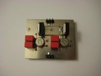
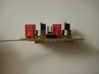
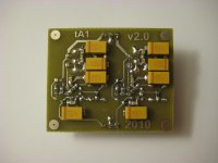
I recently finished a new board based on the LME49600 datasheet design but there is some DC offset on each channel. The offset isn't too high (15mA), but I would expect it to be lower since it uses DC servos.
Can anyone tell me why the offset is there and what I might be able to do to lower it?
Can anyone tell me why the offset is there and what I might be able to do to lower it?
Attachments
I suppose you are using schematic datasheet LM49600 page 11, move VR1-A & VR1-B both 10K till you don't have DC offset at the output, as I can check in your photos I can't see any trimmer so you must change the fixed 10K resistor for a 10K trimmer to lower the DC offset.
VR1 is the volume pot. I have this 10k pot off board and the DC offset does not change with it's position.
Did you measure and select matching surface mount resistors?
I would suspect a slight difference in resistance between them could be the problem.
I have a bit of offset on each channel with my Auzentech X-Meridian soundcard. I binned the DC blocking caps and fitted two metal canned LME47910HA into the dual socket as two singles sound a lot better than the canned dual 47920HA.
For PS caps I used 100u Nichicon polymer electrolytics; PLF1D101MDO2
Also used a 0.33u Arcotronics X rated polyprop cap across the rails, ie +ve pin to -ve pin. This is a great mod. I don't know if it would cause stability improvements or problems with this circuit with the 49600 after the OpAmp. One 0.33u sounded a lot better that one, two, or three 0.1u of the same type.
I have some Vishay bulk foil resistors to replace the surface mount ones with. Will be interested to see if that does fix the -25mV and +8mV offsets.
Last edited:
- Status
- This old topic is closed. If you want to reopen this topic, contact a moderator using the "Report Post" button.
- Home
- Amplifiers
- Chip Amps
- Lme49600 headphone amp