From the examples, I have seen capacitance ranging from 0.1 to 1000 uF, from tantalum to electrolytic bypassed with film.
What is the most appropriate type and size for the decoupling capacitor at the output, assuming cost is no object?
From my research, some seem to hint that very low ESR would cause instability for the regulator, does it mean that high ESR is prefered?
Thanks. 🙂
What is the most appropriate type and size for the decoupling capacitor at the output, assuming cost is no object?
From my research, some seem to hint that very low ESR would cause instability for the regulator, does it mean that high ESR is prefered?
Thanks. 🙂
A good start may be to see what the datasheet recommends. Don't assume that other people know what they are doing; they may just be copying each other or guessing.What is the most appropriate type and size for the decoupling capacitor at the output, assuming cost is no object?
There is no single solution. That broad range of capacitance could, on its own, be considered correct.
Werner Ogiers' voltage regulator article, and a predecessor, Reduce Noise in Voltage Regulators by Erroll Dietz (available online or as an appendix in Bob Pease's Troubleshooting Analog Circuits), are better than the datasheets at showing just how much of a balancing act is involved. A forum search for regulator output noise and output impedance will no doubt turn up more discussion on the topic.
Werner Ogiers' voltage regulator article, and a predecessor, Reduce Noise in Voltage Regulators by Erroll Dietz (available online or as an appendix in Bob Pease's Troubleshooting Analog Circuits), are better than the datasheets at showing just how much of a balancing act is involved. A forum search for regulator output noise and output impedance will no doubt turn up more discussion on the topic.
Output capacitance reduces the high frequency impedance, but eats up some of the stability margins.From the examples, I have seen capacitance ranging from 0.1 to 1000 uF, from tantalum to electrolytic bypassed with film.
What is the most appropriate type and size for the decoupling capacitor at the output, assuming cost is no object?
If you use output capacitance it is therefore necessary to also include a good input decoupling.
Provided you do that, the 78xx series can tolerate any amount of capacitance.
Combinations of large/small capacitors should be avoided, as they create "accidents" in the output impedance vs frequency curve.
No, standard regulators tolerate "perfect" caps, unlike LDO's.From my research, some seem to hint that very low ESR would cause instability for the regulator, does it mean that high ESR is prefered?
Thanks all. 🙂
I am thinking of building this:

I think I am going to copy pretty much exactly on the input side.
For the output side, I already have:
- 22uF film cap
- 40uF motor run cap
- 120uF motor run cap
I wonder if I should use them, and which one. Or do I want to get a 1000uF or so electrolytic cap. The original schematic recommends tantalum cap.
I am thinking of building this:
I think I am going to copy pretty much exactly on the input side.
For the output side, I already have:
- 22uF film cap
- 40uF motor run cap
- 120uF motor run cap
I wonder if I should use them, and which one. Or do I want to get a 1000uF or so electrolytic cap. The original schematic recommends tantalum cap.
The output impedance of the regulator is below 10mΩ up to ~2Khz.
At this frequency the reactance of even the 1000µF will still be ten times larger.
This means that you have to use the largest possible cap, in this case the 1000µF, if you want to keep the impedance as low as possible for all the audio range.
It has to be low esr, and must not be paralleled with anything, as this would ruin its characteristics at some frequency.
Obviously I have a lot to learn, because I have no idea what you are talking about. 😀 And pardon me for leaving out some important details. I intend to use this to power digital device (usb spdif).
So what I get from you is that I need a single piece of the best possible quality cap. So knowing the above, what is the minimum value should I go for?
So what I get from you is that I need a single piece of the best possible quality cap. So knowing the above, what is the minimum value should I go for?
The minimum is zero. Depends on what you want to achieve.
Electronics is a quantitative science/technique, you have to set numerical design goals from the beginning, not a pinch of this and a little more of that.
Electronics is a quantitative science/technique, you have to set numerical design goals from the beginning, not a pinch of this and a little more of that.
The device itself has its own regulator in it. My goal is to replace the noisy usb power with something better. I suppose the simplest decent linear power supply would already be better than the switching USB power from a computer. I suppose this is beyond me, so I would need to tap on your wisdom.
So to obtain lowest possible noise floor from this basic design without introducing problem that I am not even aware of 😀, which of the following would you pick for C4 if it were you?
-47000 uF electrolytic (say Mundorf)
-1000 uF solid polymer (say Sanyo Oscon)
-40 uF film (ASR motor run cap that I already have)
Or if you think I should be looking at a different design I am open as well.
The most reasonable option is the 1000µF, but the 78xx series is not top class anyway. Even a LM317 does better, and if you want to lose more time and money, there are a number of threads about "super-regulators"
I was under the impression that 78xx is superior to LM317.
http://www.diyaudio.com/forums/atta...5-19-different-ics-compared-lm317-vs-7805.zip
So it looks like I got more research to do. Thanks a lot. 🙂
http://www.diyaudio.com/forums/atta...5-19-different-ics-compared-lm317-vs-7805.zip
So it looks like I got more research to do. Thanks a lot. 🙂
A good start may be to see what the datasheet recommends. Don't assume that other people know what they are doing; they may just be copying each other or guessing.
+1
Thanks guys. 🙂
Thanks for suggesting super regulator. I found an article that says the easiest way to do this is through a 2-stage LM317 (or whatever chip).
So it got me thinking, there are many cheap LM317 assembled boards in ebay, so I could just hook 2 in series (with the first stage set a few V higher) and get a good power supply? But of course they won't be as optimized as a custom 2 stage design.
You have done your homework 🙂I was under the impression that 78xx is superior to LM317.
http://www.diyaudio.com/forums/atta...5-19-different-ics-compared-lm317-vs-7805.zip
So it looks like I got more research to do. Thanks a lot. 🙂
That kind of comparison is interesting, but can be misleading.
When you design something to specs, and you want to cover your *** (and that's a basic survival instinct), you look only at the min/max columns of the datasheet.
When you design something for yourself, or you want to know how well your masterpiece is really going to perform, you have to use pertinent information.
This table doesn't do either of them: it is based on the best typical numerical values of the datasheets.
Actual measurement of characteristics on a large enough and representative sample is the ideal, but short of that, the information extracted from the datasheet can be put to good use.
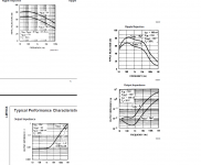
If we compare two of the characteristics emblematic for audio applications, ripple rejection and output impedance (78xx left, 317 right), we see that at first sight, the ripple rejections look rather similar: a little more than 80dB at 100~120Hz for both, with the 7805 somewhat advantaged. That is until you look at the scales: for the 317, it extends to 1MHz, instead of 100KHz for the 78xx.
This means that at 10KHz, the rejection for the 317 is still ~70dB, against 65dB for the 7805, and much worse for 78xx of higher voltages (assuming you use Cadj for the 317, which is normally the case if you are concerned with performance).
For the output impedance, the comparison is more straightforward: the 78xx has 8mΩ up to 1KHz against 2.5mΩ for the 317, both increasing to ~1Ω at 1MHz.
Both screenshots are extracted from National (now TI) datasheets. That is important, because making cross-comparison between manufacturers for such diagrams is tricky and dangerous: you have to measure them for yourself.
There are many other characteristics; many of them are much less significant for audio except noise, but that one is much more elusive, and the datasheet only provides an upper bound for it. The part to part variation can be very significant.
I have generally found that 317's are quieter than 78xx, but that is anecdotal, and there could be significant variations, both part to part and manufacturer to manufacturer. It is difficult to be categorical. If this particular parameter does really matter to you, the best option is actual comparison.
The tempco of the 317 is generally better than the 78xx, but it is relatively unimportant compared to output impedance and ripple rejection (for audio).
Attachments
Thanks again for those info. 🙂
In case you think I compiled that excel sheet, no i didn't, someone in this forum did. 🙂
So do you think a 2 stage LM317 is a good idea? Any downside to that?
In case you think I compiled that excel sheet, no i didn't, someone in this forum did. 🙂
So do you think a 2 stage LM317 is a good idea? Any downside to that?
Without ideal components, any design has a downside. You've already hit on regulator output decoupling, which is the downside to be aware of most. A 2-stage LM317 circuit will work, or you could use the tracking preregulator circuit shown in the datasheet. Feed either one with 12VDC (or a little more). The main benefit of the preregulator circuit is that the first regulator is used to maintain a constant voltage drop (~3.5V) across the second regulator, so that the second regulator's only task is maintaining load regulation.
Cascading two 317 will improve a single parameter, the ripple rejection (and line regulation). If that is what you consider to be your main problem, why not.So do you think a 2 stage LM317 is a good idea? Any downside to that?
A better option would be a second regulator markedly improving some parameter, like noise: ADP7102 datasheet and product info | 20 V, 300 mA, Low Noise, CMOS LDO | Linear Regulators | Analog Devices
Instead of using two monolithic regulators, you can also use a regulator controller with an external pass transistor. This type of regulator (a modern time version of the 723) can be very superior to a monolithic one, and can be configured to maximize some key parameter: LT1575 - Ultrafast Transient Response, Low Dropout Regulators Adjustable and Fixed - Linear Technology
Thanks a lot guys, really appreciate it.
I need at least 12V 500mA, preferably 12V 1A.
I initially wanted to do this design:
However I can not find some of the parts locally, and importing cost a bit more than I wish. So instead I managed to get most of these:

Standard textbook circuit is all I can emulate. What comes after that I am not so sure. I already have extra LM317 (Motorola) and MC7812 (On), or may be get the LT317. Either way it is already more than good enough for my use (there is further regulation and filtering in the device). But as Elvee pointed out, it seems like a lost opportunity to improve upon it.
May be some kind of simple discreet noise cancelling circuit?
I need at least 12V 500mA, preferably 12V 1A.
I initially wanted to do this design:
An externally hosted image should be here but it was not working when we last tested it.
However I can not find some of the parts locally, and importing cost a bit more than I wish. So instead I managed to get most of these:
Standard textbook circuit is all I can emulate. What comes after that I am not so sure. I already have extra LM317 (Motorola) and MC7812 (On), or may be get the LT317. Either way it is already more than good enough for my use (there is further regulation and filtering in the device). But as Elvee pointed out, it seems like a lost opportunity to improve upon it.
May be some kind of simple discreet noise cancelling circuit?
I misunderstood. I thought this new circuit would replace a 5V USB power source.I need at least 12V 500mA, preferably 12V 1A.
I misunderstood. I thought this new circuit would replace a 5V USB power source.
No, I wasn't clear. 🙂
It specified 8-14VDC for external power, I presume it is then regulated to 5V within the device. It does not mention current, so I aimed for >500mA. It can also accept AC, but I imagine such a tiny device might have a hard time handling 100Hz ripple so I opted against that.
- Status
- Not open for further replies.
- Home
- Amplifiers
- Power Supplies
- LM78xx output decoupling capacitor