power supply requirement
Hello experts. I am idiot for electronic. But I am trying to using the initial web release version to build this LM4702. But I am not very sure abouot the power supply specification require to run this amplifier.
What I know is +/- 50 for DC supply. But how much VA of power transformer to support both channels?
Do I have to get 2 same spec of transformer to run the amplifier or just a big one is enough?
Re: LM4702B
Guess what? National Semiconductor have released yet another revision to the LM4702 data sheet (Sep 2006), which is available at http://www.national.com/pf/LM/LM4702.html. I haven't been through it with a fine tooth comb yet to find out what has changed since the recent Aug 2006 release, but probably not much.
More importantly, National Semiconductor have finally made an official press release for the LM4702, dated 19 Sep 2006, at
http://www.national.com/news/item/0,1735,1192,00.html.
I have heard they are going to take LM4702 out of the Overture (tm) series and make it the first in a new series of high-performance amplifiers. It also implies that in the press release.
glennb said:Yes, the PDF data sheet has been revised for the LM4702B, which now has uprated power supply rails of +/- 100V, as against +/- 80V in the pre-announcement last year. It doesn't look like samples are available yet.
The previoulsly released LM4702C which people have been experimenting with has rail limits of +/- 75V.
The LM4702A is still under development. It will have the same rail limits as the LM4702B (+/- 100V) but in a TO-3 military compliant package, as against +/- 85V in the pre-announcement last year.
1000 Wrms into 4 Ohm anyone?
Guess what? National Semiconductor have released yet another revision to the LM4702 data sheet (Sep 2006), which is available at http://www.national.com/pf/LM/LM4702.html. I haven't been through it with a fine tooth comb yet to find out what has changed since the recent Aug 2006 release, but probably not much.
More importantly, National Semiconductor have finally made an official press release for the LM4702, dated 19 Sep 2006, at
http://www.national.com/news/item/0,1735,1192,00.html.
I have heard they are going to take LM4702 out of the Overture (tm) series and make it the first in a new series of high-performance amplifiers. It also implies that in the press release.
Check out the prices of the B & C models. For small quantities, figure $50 for the B and $300 for the C.
Pricing and Availability
Available now in a 15-lead TO-220 package, the LM4702C is priced at $4.50 in 1,000-unit quantities. The LM4702B is priced at $24.95 in 100-unit quantities. The LM4702A is priced at $150 in 25-unit quantities and will be available by January 2007. More information, easy-to-order samples and an evaluation board are available at http://www.national.com/pf/LM/LM4702.html.
Honestly does anyone really NEED the A version of this chip. I mean unless you need something that can handle voltages you can weld with there is really not much point to it.
I'm looking forward to seeing the results of everyones designs.
G.
I'm looking forward to seeing the results of everyones designs.
G.
billdinva said:Check out the prices of the B & C models. For small quantities, figure $50 for the B and $300 for the C.
Pricing and Availability
Available now in a 15-lead TO-220 package, the LM4702C is priced at $4.50 in 1,000-unit quantities. The LM4702B is priced at $24.95 in 100-unit quantities. The LM4702A is priced at $150 in 25-unit quantities and will be available by January 2007. More information, easy-to-order samples and an evaluation board are available at http://www.national.com/pf/LM/LM4702.html.
hi everyone..
LM4702(B or A) working with +-100V😱 and it's said that lm4702 is mostly suitable for high voltage transistors because of its limited current output🙁
What's the point behind desinging high-voltage power supplys? Is there any body who have a schematic for a +- 110 volts(or more) power supply? How can I supply a 600V mosfet?
Sorry for being a dummy
Yes but what does it sound like?????????
Interested in trying this IC. Technical matters not an issue, just want to now what those that have completed these amps think of them.
Interested in trying this IC. Technical matters not an issue, just want to now what those that have completed these amps think of them.
How does it sound?
Unlike most other chipamps, the output devices and topology must be chosen from a vast array of possibilities. Every combination will have different transfer and overload characteristics and hence a potentially different sound. eg. Darlingtons will be different to MOSFETS will be different to discrete Sziklai pairs.
I'm brewing up a lowish power TIP142/147 darlington amp using the LM4702 at the moment.
Progress will be reported via my LM4702 page: http://home.pacific.net.au/~gnb/audio/lm4702.html
jez said:Yes but what does it sound like?????????
Interested in trying this IC. Technical matters not an issue, just want to now what those that have completed these amps think of them.
Unlike most other chipamps, the output devices and topology must be chosen from a vast array of possibilities. Every combination will have different transfer and overload characteristics and hence a potentially different sound. eg. Darlingtons will be different to MOSFETS will be different to discrete Sziklai pairs.
I'm brewing up a lowish power TIP142/147 darlington amp using the LM4702 at the moment.
Progress will be reported via my LM4702 page: http://home.pacific.net.au/~gnb/audio/lm4702.html
I'm well aware of influence of all the various factors here😉
It's just that on this and other threads about this IC there seems to be endless ramblings about PCB's (yes I am aware of the influence of layout.......), group buys, wether to use on-semi or other devices but hardly anything about THE SOUND. If I have not allowed the protagonists sufficient time to get around to this then I apologise, but, various people seem to have managed to design PCB's, make out BOMs, build/give advice about PSUs, give links to output device app notes,discuss different output topologys......yes yes but what does it sound like?
If I had the time at the moment, I would have an amp knocked up on Vero-board (yes it can be done without ground loops, capacitive transfer between tracks etc if you are careful) or point to point wired upon the heatsink itself using tag strip within a day or two of getting a sample. I would then take a damn good listen to it and find out if the IC was capable of "audiophile" performance before spending the time and money on professional looking/made PCBs, casework, layout diagrams etc.
Not trying to "teach my granny to suck eggs" or anything guys🙂 just a different approach maybe?
Re: How does it sound?
GlennB -- did you ever consider connecting the ground pin to the high quality ground via a small resistor, or an RC network?glennb said:
Unlike most other chipamps, the output devices and topology must be chosen from a vast array of possibilities. Every combination will have different transfer and overload characteristics and hence a potentially different sound. eg. Darlingtons will be different to MOSFETS will be different to discrete Sziklai pairs.
I'm brewing up a lowish power TIP142/147 darlington amp using the LM4702 at the moment.
Progress will be reported via my LM4702 page: http://home.pacific.net.au/~gnb/audio/lm4702.html
Re: Re: How does it sound?
My current thinking is that the GND pin passes a dirty current which should be kept well away from the high quality ground trace (i/p signal), whether there is an intermediate resistor / network or not. The GND pin should be routed directly to the low quality ground (high current power supply & o/p signal).
I haven't done any subjective listening tests or objective noise/THD tests to prove my theory, I'm trying to find time to finish building an amp. Maybe by xmas. 🙁
jackinnj said:GlennB -- did you ever consider connecting the ground pin to the high quality ground via a small resistor, or an RC network?
My current thinking is that the GND pin passes a dirty current which should be kept well away from the high quality ground trace (i/p signal), whether there is an intermediate resistor / network or not. The GND pin should be routed directly to the low quality ground (high current power supply & o/p signal).
I haven't done any subjective listening tests or objective noise/THD tests to prove my theory, I'm trying to find time to finish building an amp. Maybe by xmas. 🙁
hi everyone.(sorry for my poor english)
Need help for the BJT O/P stage for newbie ss amp. design as me.
I would like to use this output stage for my amp . How I chosen the correct bias for this circuit ,(for the out put transistor I need run idling 50-100mA / piece)
Thank you very much.
Need help for the BJT O/P stage for newbie ss amp. design as me.
I would like to use this output stage for my amp . How I chosen the correct bias for this circuit ,(for the out put transistor I need run idling 50-100mA / piece)
Thank you very much.
Attachments
JustBuildLspkAS said:hi everyone.(sorry for my poor english)
Need help for the BJT O/P stage for newbie ss amp. design as me.
I would like to use this output stage for my amp . How I chosen the correct bias for this circuit ,(for the out put transistor I need run idling 50-100mA / piece)
Thank you very much.
You would probably be better off posting this in the SS amplifiers forum.
http://www.diyaudio.com/forums/forumdisplay.php?forumid=4
Maybe the moderator will move it over for you.
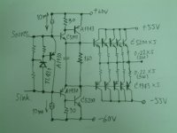
Sorry my last wording don't clear.
I will using LM4702C voltage amp drive
And using the out put stage as my last post.
...Pre-driver and driver satge 2SA1930+2SA1962/2SA1943
... Out put stage 5pairs(2SA1943/2SCC5200)
and using overall feedback
Thank you for every advise.
I will using LM4702C voltage amp drive
And using the out put stage as my last post.
...Pre-driver and driver satge 2SA1930+2SA1962/2SA1943
... Out put stage 5pairs(2SA1943/2SCC5200)
and using overall feedback
Thank you for every advise.
I connect the opamp ground to a point between the clean star-ground and the supply-decoupling-zobel-speaker ground because i think that these 3 mA's won't hurt even if dirty when passing a 2 cm trace. I isolate signal ground with a three loops air-core choke. I get no hum or noise with this design and sleep better thinking that reference grounds in the opamp stage are isolated from the extremely large decoupling and speaker return currents.
I also use "dirtiest to cleanest" arrangement in psu rails.
I also use "dirtiest to cleanest" arrangement in psu rails.
Somebody knows if there is any difference between using a vbe multiplier or a resistor in the MOSFET arrangement? National quotes THD without indicating whether it was biasing using a resistor or a vbe multiplier.
The intuitive idea is that the resistor will be more linear but will also depend more on the LM4702 current source stability.
Any clues?
The intuitive idea is that the resistor will be more linear but will also depend more on the LM4702 current source stability.
Any clues?
If you are referring to the AN-1645 note about using the LM4702 to drive MOSFETs, then it should be clear a resistor is being used for those FETs that do not need thermal compensation. I believe the Magnatec and Renesas ones do not. The Toshiba FETs need thermal compensation so a Vbe multiplier is used for that set up. I forget what is done with the IR's but they could not be fully biased because of the limitation of the bias voltage using the LM4702. I don't know that there is a big difference in THD between the Vbe or resistor bias. I believe it has more to do with simplicity in design.
-SL
-SL
SpittinLLama said:I don't know that there is a big difference in THD between the Vbe or resistor bias. I believe it has more to do with simplicity in design.
With the LM4702 + IRF/Vishay MOSFET's you can't really get the bias high enough to drop the THD% -- but you can get it to work, and to a level which is close to acceptable. The 240/9240's are relatively inexpensive, but the '1058/162s aren't that much more.
Yes, i plan to use 2SK1530 & 2SJ201. I know that these need thermal compensation but i may use a resistor and a huge heatsink with a fan if this has to give better sound.
It's interesting to note that the Vbe multiplier should have much lower differential impedance than the resistor. Assuming that the source pin cannot sink current and that the sink pin cannot source current that would create a longer time constant for turn off so high frequency signals would be reproduced in class A.
National seems to introduce the Vbe multiplier only as a way to add thermal compensation with no effect on THD.
I have already listened to IRFP240/IRFP9240 in other designs and i don't like them.
hi, just wanna ask is it possible to use 2SD2488 and 2SB1620 darligtons in building amp with Lm4702, i have 5 pairs tooked from Sony HT receiver, and wanna build something that would sound good but also have enough power (maybe using a multiple darlingtons at output?)
so I would appreciate if someone`d be kind to tell me how to do that in schematic, I am a quite newbie with this stuf
so I would appreciate if someone`d be kind to tell me how to do that in schematic, I am a quite newbie with this stuf
- Status
- Not open for further replies.
- Home
- Amplifiers
- Chip Amps
- Lm4702