
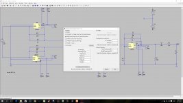

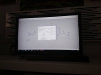
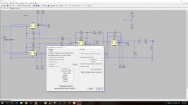
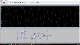
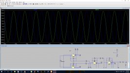
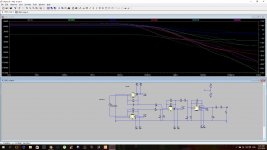
Your transient run looks to have infinite gain. The voltage source V3 needs to simulate the output impedance of the dac ? or perhaps use a current source instead.
Your transient run looks to have infinite gain. The voltage source V3 needs to simulate the output impedance of the dac ? or perhaps use a current source instead.
I wanted to see why when I changed the values of resistors in the non inverter op amp from 2k to 1k vishay dale 0.1
the op amp stop work (the gain is 2)
I know that you have downloaded the values of resistors reduces the noise
But this is probably related to the slaw rete of the lm4562
the low pass filter before the op amp 79khz -3db
1670hom - cap 1.2n
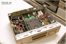
I did optimized to DAC
I got rid of the CIG FILTER
And I changed a lot of values and the denon sounds amazing.
But changing the resistor value did not work as expected
(I returned to 2K and everything worked back)
Maybe I need to change in addition to the feedback capacitor 10P to make it work.
Attachments
-
 12622557_3130190656976_8608355481245662488_o.jpg258.5 KB · Views: 210
 -
 12658043_3130185416845_2184966213938764266_o.jpg182 KB · Views: 94
 -
 12717726_3134383881804_2110428560832395882_n (1).jpg84.5 KB · Views: 57
 -
 12669411_3134384201812_2099092242956050894_n.jpg33.2 KB · Views: 74
 -
 12688273_3134383761801_703314777100709698_n (1).jpg75.5 KB · Views: 81
 -
 12654424_3134342760776_669323676323929787_n.jpg64.5 KB · Views: 96
 -
 12705240_3134384041808_5045985725269837714_n (1).jpg40.2 KB · Views: 65
Last edited:
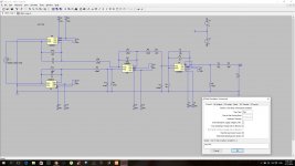
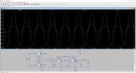
use my mod broTry just putting 1 in the voltage if you need 1mv try 0.001
pic of my voltage attached.
Which lm4562 model do you have. I've been unable to get the one I downloaded from TI (which looks like it is a very comprehensive model) to work.
Tony.
Attachments
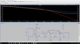
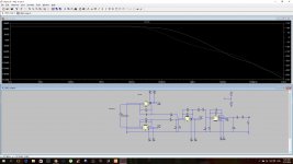
If you look at the scale on your sim you will see it is showing nearly 160db gain. You also have the X axis going out to 1GHz.
This isn't so very different from yours. Look at the scale(s)

This isn't so very different from yours. Look at the scale(s)
Why do you need Lf filter at output-1200pF or 1000pf ...I don*t see clearly... big capacitive load for 4562!? Isolation resistor helps a bit but I think it is too big.
If you look at the scale on your sim you will see it is showing nearly 160db gain. You also have the X axis going out to 1GHz.
This isn't so very different from yours. Look at the scale(s)
View attachment 530448
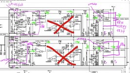
mooly you have a formula through which I can determine the ideal ratio (I think you're definitely one of the experts in the OP AMPS)
gain of 2 r2/r1 +1
Lowest resistance resistors values
Amplifier can remain stable in SLOW RETE
IC303
IC304
I think that if I lower the value resistors from 2K
To 1K.
So I have to increase the value from feedback capacitor 10P to ?
naw its 7961783hz (10p /2khom)
Attachments

Last edited:
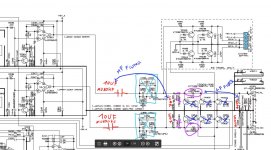
do You meanWhy do you need Lf filter at output-1200pF or 1000pf ...I don*t see clearly... big capacitive load for 4562!? Isolation resistor helps a bit but I think it is too big.
To DC CAPS
in the output stage ?
No way I remove them protecting my speakers
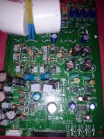
Originally there were values 470P
And changed to 1N
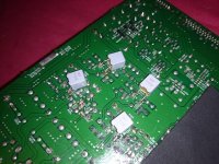
That originally was resistors in series 300 hom
And changed to 150HOM
So now they filter about 1GHZ
(470P bass sounds less balanced)
Attachments

do You mean
To DC CAPS
in the output stage ?
No way I remove them protecting my speakers
??? i dont understand what you are talking about?
DC is filtering with 10uf Mundorf
AC noise is filtering with RC filter ...and another ways.
Originally there were values 470P
And changed to 1N
That originally was resistors in series 300 hom
And changed to 150HOM
So now they filter about 1GHZ
What wil 1Ghz filter help you amplifier?
(470P bass sounds less balanced)
can you describe ...sounds less balanced.. in comparisson to? midrange ?
There is no magic formula.
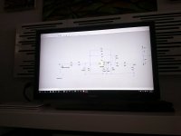
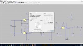
If you want to experiment with altering and lowering values and deleting parts of the original circuit then you first need to set up a sim of the circuit as it stands now (original manufacturers version). Then 'copy' that in LT (copy is in the top row of tools) and paste the copy next to the original. So you now have two identical versions. Make the voltage rails common to both and make the inputs common to both. Now you can run the sim and alter the right hand version and see the effect compared to the original. This is the only way you will maintain any reality of what the changes are doing to the response.
(no off the shelf components are going to behave as you think at 100MHz, let alone 1GHz)
I worked on this project a yeardo You mean
To DC CAPS
in the output stage ?
No way I remove them protecting my speakers
??? i dont understand what you are talking about?
DC is filtering with 10uf Mundorf
AC noise is filtering with RC filter ...and another ways.
Originally there were values 470P
And changed to 1N
That originally was resistors in series 300 hom
And changed to 150HOM
So now they filter about 1GHZ
What wil 1Ghz filter help you amplifier?
(470P bass sounds less balanced)
can you describe ...sounds less balanced.. in comparisson to? midrange ?
and resume
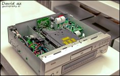
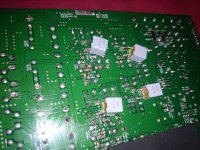
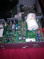
i did a lot of changes in Danon both 3910 and the denon 2900.
(the denon 3910 was my first project since I did a lot of other projects)
Years I did no work on the project.
And returned.
The first change I made my return to work for Danone would change the 30K resistor
To 100K
It has affected a lot about sound better.
With capacitors 470P
Although it's weird. The bass was less accurate
When I switched capacitors 1N LCR
It was perfect.
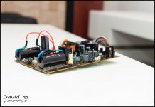
I also added
dcoupling capacitor to 4562
It was the most significantly influenced make the sound better.
I could not believe how good the 4562 until he did it.
In addition to filter CIG who was the I / V of the buffer was removed.
I had no idea how the CIG
The ruins of the sound.
What I love about project to see how math formulas affect.
I'm old school always like working with paper and pencil.
This is the first time I worked with software such as LTSPICE and TINA
So learning to use this software Although not trust them too much 😉
Attachments
-
 1799887_2392534136024_1285111010_o.jpg209.6 KB · Views: 112
 -
 1598842_2391797917619_1011790425_o.jpg246 KB · Views: 115
 -
 1782343_2391488629887_1488201964_o.jpg92.9 KB · Views: 114
 -
 12705403_3135004177311_4646320823810123891_n.jpg131.2 KB · Views: 56
 -
 12688210_3135003897304_7660498875152086460_n.jpg100.4 KB · Views: 106
 -
 12687988_3135004057308_714795940464810656_n.jpg99.4 KB · Views: 113
 -
 12688163_3135004497319_1504971129483492774_n.jpg100 KB · Views: 69
Last edited:
use my mod bro
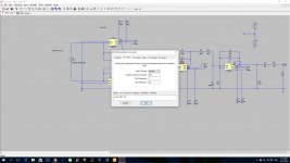
OK well that is weird!! I just loaded your circuit, and it works (with minor fix for C5) for ac analysis. It just picked up my lm4562 model and works.
I get an error, time step too small if trying to run transient though.
If I use the lm4562 in my own circuit it gives me errors about nodes within the model... odd.
Tony.


100khz
Attachments
Last edited:
You might find bits of this interesting.
(I see you switched to a current source to emulate the DAC output)
https://www.by-rutgers.nl/IV-converter.html
(I see you switched to a current source to emulate the DAC output)
https://www.by-rutgers.nl/IV-converter.html
You might find bits of this interesting.
(I see you switched to a current source to emulate the DAC output)
https://www.by-rutgers.nl/IV-converter.html
thanks mooly 🙂
So much useful information on one page
Last edited:
You might find bits of this interesting.
(I see you switched to a current source to emulate the DAC output)
https://www.by-rutgers.nl/IV-converter.html
ammm
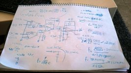
if the formula of slew rate is
slew rate= 2πfV
the slew rate of lm4562 is
20V/µs = 20000000Vs
vcc= 9
vee=-9
18v peak-to-peak
so
20000000=2*3.14*18*f
so the max frequency that the LM4562 can supply 18 v
is
20000000
----------- =176928hz
2*3.14*18
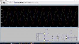
so max frequency that the LM4562 can supply 2v peak-to-peak
is
1592356hz

So I think I'm coming close to solving why replacing resistors. 2K to 1K
Made the 4562 to not work
2k - 10p =7961783.4394904 Hz
1k - 10p =15923566.878981 Hz

Last edited:
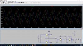
That's right, the max frequency something like an opamp can pass undistorted (for a sine wave) is,
F = Sr/(2pi * Vout peak) so that's 20E6 (6.28*18) which is your 176928Hz
Anything over that and the waveform will tend to distort to a triangular shape. You can take the theory further and look at the step response as well.
Once the peak output voltage of a step waveform divided by the rise time of the opamp exceeds the opamp slew rate then you have run into slew rate limiting.
- Status
- Not open for further replies.
- Home
- Source & Line
- Digital Source
- lm4562 ltspice transient ?