i test naw in spice 1k resistor valueThat's right, the max frequency something like an opamp can pass undistorted (for a sine wave) is,
F = Sr/(2pi * Vout peak) so that's 20E6 (6.28*18) which your 176928Hz
Anything over that and the waveform will tend to distort to a triangular shape. You can take the theory further and look at the step response as well.
Once the peak output voltage of a step waveform divided by the rise time of the opamp exceeds the opamp slew rate then you have run into slew rate limiting.
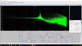
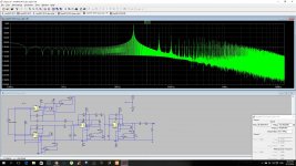
in transient f=100k
in the output of the final op amp this spike
Attachments
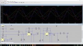
Simulation can sometimes throw up odd artefacts that aren't really there in the real version.
http://www.diyaudio.com/forums/powe...-high-voltage-into-constant-current-sink.html
http://www.diyaudio.com/forums/powe...-high-voltage-into-constant-current-sink.html
Simulation can sometimes throw up odd artefacts that aren't really there in the real version.
http://www.diyaudio.com/forums/powe...-high-voltage-into-constant-current-sink.html
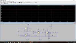
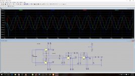
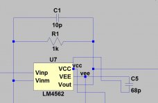
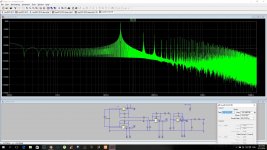
i naw run test with feedback cap
Instead 10P
100P
With 1K resistor
This will filter out the higher frequencies better
instead of 2k -10p =7961783hz
1k - 100p =1592356hz
I think it improves the slew rate performance of the 4562
(the original op amp was njm2068 Perhaps the capacitors with this small value Designed for his spec )
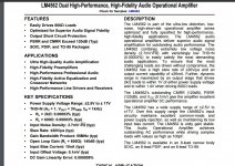
Data sheet of the LM4562
Talk about capacitors 100P
And if you could expand on this subject
i always was curious this figure
What do you think mooly ?
Attachments
Last edited:
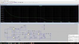
I'm not really sure what you are trying to achieve in all this. The bigger you make C1 and the earlier the stage will start to show a falling response.


Last edited:
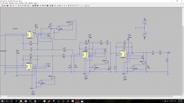
class a vs class ab
10k resistor - op amp out to vee -0.9ma
Its not easy to assimilate it from pictures... so what's the bottom line as you see it, A vs AB in simulation ?
Its not easy to assimilate it from pictures... so what's the bottom line as you see it, A vs AB in simulation ?
from the test
in class a the noise begin in 60nV and drop to 40nV in 100 hz
and in class ab 160nV and drop to 40nV in 200hz
in class a and class ab
output 69db and drop tp62db 100hz
20khz ac analysis
class a (4700 hom biass resistor 1.8ma)

class ab

I honestly wouldn't like to say one way or the other on that. I think you will find the real implementation will be nothing like the sim if you actually measured it with test equipment. You are way down below the natural noise of all the circuitry when you are talking nano volts.
I honestly wouldn't like to say one way or the other on that. I think you will find the real implementation will be nothing like the sim if you actually measured it with test equipment. You are way down below the natural noise of all the circuitry when you are talking nano volts.
mooly do You think
The practical worth to make the LM4562
into Class A ?
The simplest form of a resistor op amp output to VEE
That disadvantage I lose the option to use of the decoupling capacitors
VEE to ground
VCC to ground
So too is the logical Class A will be a bit more noisy
Although under test in LTSPICE
I can still use
bypassing capacitor between 4 to 8 (68nf)
mooly do You think
The practical worth to make the LM4562
into Class A ?
I would say no benefit. If you look at the hf noise and hash on the rails in your player you will probably find it measurable, even on a scope. A resistor simply introduces that noise into the opamp output node... yes the opamp output sinks it all but you are making it work to do that, and it won't be 100% effective at the frequencies involved.
I would say no benefit. If you look at the hf noise and hash on the rails in your player you will probably find it measurable, even on a scope. A resistor simply introduces that noise into the opamp output node... yes the opamp output sinks it all but you are making it work to do that, and it won't be 100% effective at the frequencies involved.
thanks mooly


FFT (Fast Fourier Transform), not FET 🙂
It is showing you a plot of the amplitude of the output voltage and any harmonics present. The input voltage is referenced to 0db = 1.414 volts peak (1vrms). So if you set your source voltage to 1.414 volts and look at its FFT you will see a single spike corresponding to the frequency of the input and its amplitude. If you look at the output voltage then you can see how much gain or attenuation there is and what nasties have been added.
Have a look at post 19 and 20 here,
http://www.diyaudio.com/forums/soft...ng-ltspice-beginner-advanced.html#post4031841
FFT (Fast Fourier Transform), not FET 🙂
It is showing you a plot of the amplitude of the output voltage and any harmonics present. The input voltage is referenced to 0db = 1.414 volts peak (1vrms). So if you set your source voltage to 1.414 volts and look at its FFT you will see a single spike corresponding to the frequency of the input and its amplitude. If you look at the output voltage then you can see how much gain or attenuation there is and what nasties have been added.
Have a look at post 19 and 20 here,
http://www.diyaudio.com/forums/soft...ng-ltspice-beginner-advanced.html#post4031841
thanks mooly
but if i set my source to 1.414v the circuit wil not work
i also try a small experiment
standard vs class a - JFET Cascode
Attachments

Last edited:
You would have to use an input current that gave a measured 1vrms at the output (if that is what you want).
I don't know what you are trying to achieve. Adding class A biasing imo isn't going to better anything. Anything you alter that changes the response of the DAC filter can only take the stage further and further from its original design.
I don't know what you are trying to achieve. Adding class A biasing imo isn't going to better anything. Anything you alter that changes the response of the DAC filter can only take the stage further and further from its original design.
You would have to use an input current that gave a measured 1vrms at the output (if that is what you want).
I don't know what you are trying to achieve. Adding class A biasing imo isn't going to better anything. Anything you alter that changes the response of the DAC filter can only take the stage further and further from its original design.
It's only theoretical experiments.
To learn and evolve.
It does not mean I'll put it to my Denon.
All this started Affairs of curiosity about 2 resistors that have disabled innocent LM4562 .
I have to learn as much as possible for a future project of transforming the Danon audio circuit
To DUAL MONO - PCM1796 Per channel
So I have to improve my Design and analysis circuit
That I will have to plan.
All DAC from new
(in the Denon 3910
There are two PCM1796 One of the STEREO DOWNMIX And other stereo.)
Last edited:
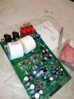
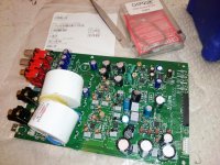
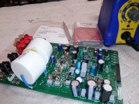
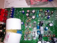
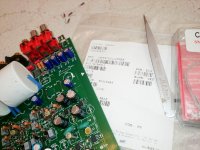
i solder buck the resistors 1.2K
VISHAY -RN55 -0.1 %
To my surprise, everything is working even better than before
DC offseton in the rca output is 0.1 millivolts .
So probably the LTSPICE
And all my math calculations was not wrong
VISHAY -RN55 -0.1 %
To my surprise, everything is working even better than before
DC offseton in the rca output is 0.1 millivolts .
So probably the LTSPICE
And all my math calculations was not wrong
Attachments

Last edited:
DC offseton in the rca output is 0.1 millivolts .
The output is AC coupled according to the diagrams 😉 so the offset should always be zero.
The output is AC coupled according to the diagrams 😉 so the offset should always be zero.
Almost 0
At least one good thing came out of all what story
I learned to use the software LTSPICE
It would help me next project to build an amplifier of NELSON PASS - the m2
I just need to check if the store of DIYAUDIO
Sending parts to Israel
Although I have a excellent amplifier
* BMC AUDIO CS2 😉
I want to build an amplifier
To advance my abilities
Last edited:
Almost 0
Almost zero is good enough. There is a reason why a meter doesn't show zero for the offset but its something you can't change.
Don't know on the store question. You would have to ask in the store thread.
- Status
- Not open for further replies.
- Home
- Source & Line
- Digital Source
- lm4562 ltspice transient ?