These ICs have current programming. That makes the output switch differently (no series resistor is used with current programming).
As long as the resistor is in series with each LED, that will allow the IC switching to go to ground which should eliminate the problem of LED1 remaining lit.
As long as the resistor is in series with each LED, that will allow the IC switching to go to ground which should eliminate the problem of LED1 remaining lit.
I understand.
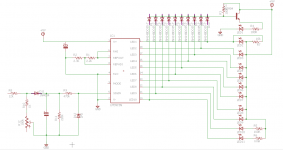
I'll have to purchase a few more 1k's to test that - Attached is the schematic you asked for.
If you don't mind, I'd like to address another section of this instrument - the power supply.
I will be installing this in my vehicle, and I'd need to have a constant power source + ACC turn on.
I think running the LM and LED's at 5v would be best, so a voltage regulator + transistor switch would be needed. Something that can do 300-500mA should be solid enough. How should I approach this?
I'd like to keep footprint as small as possible so I'm hoping I can use a TO-92 transistor to hold 500mA @12V and an SMD LM7805 to regulate 5v.
Attachments
To test to see if the 1 k in series would blank LED1, you only need the resistor in series with one LED and that LED be lit (its output pin pulled to ground).
You'll have to test with the 5v regulator. IF it runs too hot, you can add a sink to it or go to a 7809.
Why do you need a constant source? All you need is a switched source?
You'll have to test with the 5v regulator. IF it runs too hot, you can add a sink to it or go to a 7809.
Why do you need a constant source? All you need is a switched source?
I don't want to power it off the Pioneer HU remote lead.
I'd rather have a constant source and use the remote from the HU to turn it on, something like the turn on circuit for a switching power supply (in your sig)
I'd rather have a constant source and use the remote from the HU to turn it on, something like the turn on circuit for a switching power supply (in your sig)
I'd assumed that it was going to be mounted where you could see it when driving. If it's not, there are many options for switching.
It will be mounted below the HU.
But I do have two amplifiers and a 3 wire volt meter being switched on from the HU remote on, and I dont want to overload it.
But I do have two amplifiers and a 3 wire volt meter being switched on from the HU remote on, and I dont want to overload it.
Im using a Can-bus adapter to get acc for the HU, as its a new vehicle.
Its a Connects2 unit - not sure how much current it can provide.
Its a Connects2 unit - not sure how much current it can provide.
I have two updates:
1. I purchased a regulated 12v power supply - it will output 12v @ 200mA with input voltage as low as 2.5v - I can use an acc power up circuit on it.
2. I tested the circuit with 1k resistors between LM pins and LED's, with the diodes tapped of in between the diodes and LEDs - no change, 1st led is always lit.
Are the output pins of the IC now driving all of the way to ground?
If not, change the current limiting/programming for the outputs to no current limiting (only do this if there are resistors in series with ALL LEDs).
If not, change the current limiting/programming for the outputs to no current limiting (only do this if there are resistors in series with ALL LEDs).
With 1k resistors on pin/LED I'm measuring 4.6 volts with 4.7k resistor between pin 7-8 and a 10k between 8 and ground.
Do I just bridge pin 7 to 8 to cancel current limiting?
Do I just bridge pin 7 to 8 to cancel current limiting?
It appears that bridging pin 7-8 will make all leds light up faintly.
I put in 680 ohm resistor on pins 7-8 to get around 23mA of current. I put 1k between pin 8 and ground (sets a 3v input range).
I then measured ground to LM pins - 0.5 volts. Just not enough to pull to ground and switch that first led off.
If I had on each pin, two or three leds in series, it would have been enough to pull the LM pins to ground.
It seems like I'm going to have to ditch the dot mode and go graph mode, I'm pretty bummed about that.
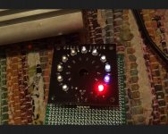
I had another go at it today.
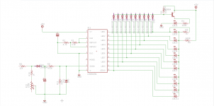
LEDs 1-9 are white (forward voltage of 3v), LED 10 is blue (forward voltage of 3v) and LED 11 is red (forward voltage of 1.8v)
I've placed a 680 ohm resistor on the LED supply & set the LM to output around 3.8mA of current via a 3.3k resistor between pins 7 and 8. Also placed a 4.7k resistor between pin 8 and ground to achieve a full scale voltage of 3.02v
Here is the updated schematic:

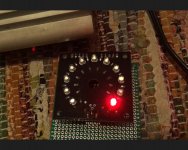
Now, this all works great, except for when the last led (red) lights up - I can see LEDs 6-10 light up very faint as well for a few seconds as if it flashes on and off.
LED 10 on (9 on LM)

LEDs 6-11 on (5-10 on LM) - This is the issue

LED 11 on (10 on LM)

I found this in the application hints
From my understanding, I need to add a small capacitor between pin 7 and ground, as this may be due to oscillation?
LEDs 1-9 are white (forward voltage of 3v), LED 10 is blue (forward voltage of 3v) and LED 11 is red (forward voltage of 1.8v)
I've placed a 680 ohm resistor on the LED supply & set the LM to output around 3.8mA of current via a 3.3k resistor between pins 7 and 8. Also placed a 4.7k resistor between pin 8 and ground to achieve a full scale voltage of 3.02v
Here is the updated schematic:
Now, this all works great, except for when the last led (red) lights up - I can see LEDs 6-10 light up very faint as well for a few seconds as if it flashes on and off.
LED 10 on (9 on LM)
LEDs 6-11 on (5-10 on LM) - This is the issue
LED 11 on (10 on LM)
I found this in the application hints
Application Hints
The most difficult problem occurs when large LED currents are being drawn, especially in bar graph mode.
These currents flowing out of the ground pin cause voltage drops in external wiring, and thus errors and oscillations. Bringing the return wires from signal sources, reference ground and bottom of the resistor string to a single point very near pin 2 is the best solution.
Long wires from VLED to LED anode common can cause oscillations. Depending on the severity of the problem 0.05 μF to 2.2 μF decoupling capacitors from LED anode common to pin 2 will damp the circuit. If LED anode line wiring is inaccessible, often similar decoupling from pin 1 to pin 2 will be sufficient.
If LED turn ON seems slow (bar mode) or several LEDs light (dot mode), oscillation or excessive noise is usually the problem. In cases where proper wiring and bypassing fail to stop oscillations, V+ voltage at pin 3 is usually below suggested limits. Expanded scale meter applications may have one or both ends of the internal voltage divider terminated at relatively high value resistors. These high-impedance ends should be bypassed to pin 2
with at least a 0.001 μF capacitor, or up to 0.1 μF in noisy environments.
From my understanding, I need to add a small capacitor between pin 7 and ground, as this may be due to oscillation?
Attachments

- Status
- Not open for further replies.
- Home
- General Interest
- Car Audio
- LM3915 based VU meter