Thank you AndrewT,
This is a lm3886 YuanJing bought on ebay and I discover a long thread about it... (you wrote also on this thread) most of user seems to be enough happy about it but clearly my lack of knowledge is not playing a good role.
Sad to say that in the first configuration it was working and sounding great!
Do you have any suggestion as a starter kit easy for a complete newbie?
Thanks again for the support!
Luca
There are Members of this Forum offering PCBs and kits.
There are reports from our Members of other semi-commercial offerings. When Members regularly give good reports on the customer service and support, then you can expect similar
There are reports from our Members of other semi-commercial offerings. When Members regularly give good reports on the customer service and support, then you can expect similar
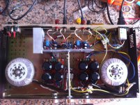
My suggestion: Get better cooling for the chip on right. Many active speakers do something similar as what you've done and the chip further away from the main heatsink tend to be the first to die. Except in your situation the metal connecting everything together is even thinner and your main heatsink looks like it can do 20W if it had a fan. Y'know what, get better cooling period.
Thank you for the advice, It does not seem getting warm but improving the heatsink was already in the plans, I need to find a nice solution for the implementation !
Test it.
Take off the speakers.
Attach an 8r0 dummy load. 5W will do for each channel.
apply a continuous sinewave test signal so that both channels are delivering 1W to their respective 8r0 load.
Measure how long it takes for the chips to get too hot to touch.
I was surprised by how quickly the chipamps get hot delivering only 1W, even though I had read and understood the graph in the datasheet showing the device dissipation vs output power for a small selection of supply voltages.
Thank you AndrewT,
This is a lm3886 YuanJing bought on ebay and I discover a long thread about it... (you wrote also on this thread) most of user seems to be enough happy about it but clearly my lack of knowledge is not playing a good role.
Sad to say that in the first configuration it was working and sounding great!
Do you have any suggestion as a starter kit easy for a complete newbie?
Thanks again for the support!
Luca
Sure, try the Modulus86.
It's not the cheapest, but I am enjoying it.... build instructions are good, and there are projects on Mouser so you can buy all parts without searching for them. Just make sure Mouser has all the parts in stock after you put them in your cart. You still need to get a heatsink and a box for it.
Hello guys! I have a problem with my LM3886 Amp and i seek some special help 🙂
I have a circiut like on chipamp.com with 50k potentiometer.
The power supply is regulated, based on LT1083 - Vin 26V , Vout 22V.
Standalone power supply works well, both rails are +22v ; -22V ... when i connect it to LMs the positive rail is dropping to something about 3V ?!
The DC output is about 5mV. Amplifier works and souds good... I noticed that issue when I saw that positive rail regulator is very hot. Point is that the voltage drops not every time sometimes it is normal +22V and i have no clue what is wrong.
Ofcourse i check every soldier point a few times and Im hopeless...
Forgot to mention that the power supply schematic is like here:
Pedja Rogic Audio Pages - Chip Based Power Amp i.e. Gainclone - Regulated Supplies
but instead of LM338 i have LT1083 , before the regulator is 10000uF and C1, C2 are 10uF.
Please Help
Pedja Rogic Audio Pages - Chip Based Power Amp i.e. Gainclone - Regulated Supplies
but instead of LM338 i have LT1083 , before the regulator is 10000uF and C1, C2 are 10uF.
Please Help
remove the amplifier and test the two regulators using a dummy load.
Problem solved in this topic:
http://www.diyaudio.com/forums/tube...nteresting-startup-problem-2.html#post4305748
See advice in my post.
Thank You for advice.
In addition I have another qustion 🙂
I have 470uF on output of LT1083 and after 10cm of wire is 1000uF + 100nF on 3886 chip legs.
Question is... is this 470uF necessarly or should i change it to combination 22uF + 4,7uF and on chip pins 1500uF+100nf or something else? I have a feeling when i added 470uf (firstly i have no capacitor there) my bass is a little thinner...
An externally hosted image should be here but it was not working when we last tested it.
This is my simplified circiut. Im looking for the best capacitor configuration after voltage regulator. On neurochrome audio Tom suggests 1000uf+4,7uF+22uF on chips pins instead 1000uF +100nF but he consider circiut with no voltage regulator.
Last edited:
What is the transformer you have used, is it with dual secondary...
Gajanan Phadte
Of Course...
I removed the 470uF capacitor yesterday sonicaly it wasnt doing any good.
Why are you reducing the 26Vdc down to 22Vdc?
Lower Voltage supply sound little bit calmer and its good to have Vin-Vout = 4V am I right? 🙂
- Status
- Not open for further replies.
- Home
- Amplifiers
- Chip Amps
- LM3886 works in a few seconds then it shut off.