The secondary voltage (24V AC) is probably about half of what is should be.
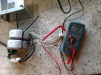
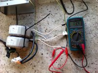
Try measuring the voltages of the PSU, input AC and output DC.
Try measuring the voltages of the PSU, input AC and output DC.
Hi Mark,
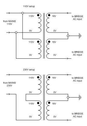
I initially connected both primary to the 220 (First schema) and the secondary was providing 48v so I moved to the second schema and it is providing 24 volts.
Luca
I initially connected both primary to the 220 (First schema) and the secondary was providing 48v so I moved to the second schema and it is providing 24 volts.
Luca
I did and between the ground and each inputs is 24 while between the inputs is 48.Should not too much 48V once will be rectified ?
in the bridge I bought, it is written 26 volts so I am worried that if I connect 48v it will burn everything....
in the bridge I bought, it is written 26 volts so I am worried that if I connect 48v it will burn everything....
Last edited:
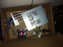
The PSU was made for 2x26V.
If you look at the schematics in post #43, you would measure 18V AC between one secondary and ground. The combined voltage of the two secondaries is 36V AC.
If you look at the schematics in post #43, you would measure 18V AC between one secondary and ground. The combined voltage of the two secondaries is 36V AC.
Hi Mark
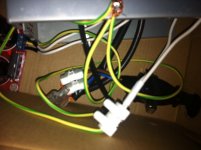
I posted some pictures with the differents configuration, could you please advice which is the correct one?
Thanks again!
I posted some pictures with the differents configuration, could you please advice which is the correct one?
Thanks again!
Attachments
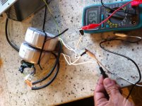
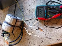
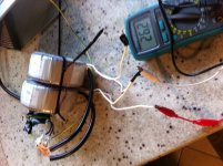
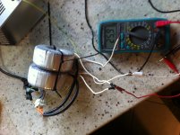
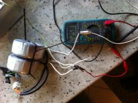
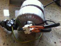

Photo's 4 to 9 show the correct way to connect the transformers for 26-0-26 Volt.
Don't use the green/yellow wire to connect the transformers secondaries to the chassis (mains earth). Connect the 4 transformer leads to the inputs of the PSU with 2 of the wires connected to the PSU ground. Connect a wire between the PSU output ground and chassis.
Don't use the green/yellow wire to connect the transformers secondaries to the chassis (mains earth). Connect the 4 transformer leads to the inputs of the PSU with 2 of the wires connected to the PSU ground. Connect a wire between the PSU output ground and chassis.
Last edited:
Hi Mark,
I tried the configuration but when I connected to the chip I heard a sparkling.
I dismount and reset in the previous configuration but now one of the two channels is not working anymore and on the audio out I can see 12-13 volt, what can I do to understand which component is failing?
Thanks
I tried the configuration but when I connected to the chip I heard a sparkling.
I dismount and reset in the previous configuration but now one of the two channels is not working anymore and on the audio out I can see 12-13 volt, what can I do to understand which component is failing?
Thanks
Checked and they are connected, I also tried better the second channel and it is making a lot of noise 🙁
I definitevely think that I have burned everything 😡😡, I am going to order a new kit and use the previous working configuration.
I definitevely think that I have burned everything 😡😡, I am going to order a new kit and use the previous working configuration.
There are several suspect solder joints, try re-soldering.
I have had the feedback loop fail a few times and it did not damage the LM3886, it does damage/destroy the speaker though.
Good time to build a http://www.diyaudio.com/forums/power-supplies/167579-light-bulb-tester.html#post2200138.
I have had the feedback loop fail a few times and it did not damage the LM3886, it does damage/destroy the speaker though.
Good time to build a http://www.diyaudio.com/forums/power-supplies/167579-light-bulb-tester.html#post2200138.
Attachments
Last edited:
these comments will not sort your problem.
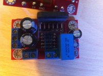
That big input? capacitor has some odd marking that I don't understand.
It states:
4µ7K100 X2
That reads to me as:
4µ7 = 4µ7F
K = ±10% tolerance
100 = maximum voltage of 100Vdc
X2 = X rated capacitor for use on mains supplies upto 250Vac and usually rated for 275Vac maximum.
The 100 and the X2 contradict each other which makes me suspicious of what the capacitor is purported to be.
Why have you used a 4u7F input capacitor?
There does not appear to be any HF decoupling for the supply rails. Is it installed on the underside?
Last edited:
Hi Andrew,
This is a Chinese preassembled kit, I don't have the skills to answer your question but perhaps Mark can as it seems he has the same version.
Luca
This is a Chinese preassembled kit, I don't have the skills to answer your question but perhaps Mark can as it seems he has the same version.
Luca
I think this is not a kit but a ready made amp. If one of the capacitors came off in the post already, enough reason to suspect all the solder work.
I getting crazy, yesterday while I was doing additional tests on the LM3886 suddenly it burnt itself..... I don't know if does it make sense to replace only the chip or to throw everything away and reorder the kit....
I am just thinking if it would be possible that all test weakened the chips and this is the reason to make it burn... but I am not really sure also if the rectifier is working properly...... I am getting in confusion....
I am just thinking if it would be possible that all test weakened the chips and this is the reason to make it burn... but I am not really sure also if the rectifier is working properly...... I am getting in confusion....
- Status
- Not open for further replies.
- Home
- Amplifiers
- Chip Amps
- LM3886 works in a few seconds then it shut off.