Is this Design is ok
Hi Availlyrics
Is your posted design of LM3886 PDF is tested ok
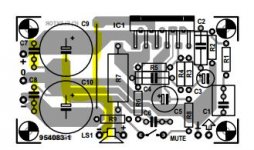
Have a look at this elektor electronics magazine design
Hi Availlyrics
Is your posted design of LM3886 PDF is tested ok
Attachments
Last edited:
Yes it is oké except for one thing: C7 and C8 are to far from the power supply connections of the LM3886. So what you have to do is to put two capacitors of 100 nF on the backside of the PCB which are connected two the + and - connections of the LM3886 and the earth of the power supply.
Marc.
Marc.
Hi Availlyrics
Is your posted design of LM3886 PDF is tested ok
Yes it works.
Elektor board not too good
The elector layout has a few things that could be better.. just have a look at the grounding arrangement Output current will interfere with audio ground . I have highlighted the offending area. Also the decoupling caps in wrong place too
The elector layout has a few things that could be better.. just have a look at the grounding arrangement Output current will interfere with audio ground . I have highlighted the offending area. Also the decoupling caps in wrong place too
Attachments
Yes it works.
Hi availlyrics
I cant found same value input capacitor (C1) can you have any suggestion or equivalent for (C1). can i use any non electrolytic or electrolytic capacitor.please help me
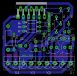
The PCB traces shown in post45 have 3 different tappings from the Zero Volt trace between the PSU smoothing Caps.
This is WRONG.
It is the worst example of bad practice I have ever seen.
There must be ONE trace from the Zero Volts and then the star feeding a reference voltage to any other parts of the circuit that need that reference.
There are two decoupling capacitors added at the power input. These are in the WRONG place. DO NOT fit them there.
I have not examined the rest, but if the layout designer got those two parts so wrong, then it probably means there are other parts that are wrong as well.
Last edited:
I think its one of the worst designs out there.
Its overrated piece of crap. Seems that I have to make one.
Someone used that design and hes amp blew up.
Its overrated piece of crap. Seems that I have to make one.
Someone used that design and hes amp blew up.
I am finding it hard to believe ELEKTOR would publish such a poor layout . To me the PCB looks like a jumbled mess
Scrap it and start again.. keep psu componets to the left side of the pcb! the shorter you can get the tracks the better. To be honest that is one of the worse I have seen . I will leave the rest to Andrew.. I suggest you have a good look around the forum there are some good layouts on here . No point in building a poor amplifier down to layout.. If you post the eagle file I will have a go at a layout for you ..
Last edited:
Scrap it and start again.. keep psu componets to the left side of the pcb! the shorter you can get the tracks the better. To be honest that is one of the worse I have seen . I will leave the rest to Andrew.. I suggest you have a good look around the forum there are some good layouts on here . No point in building a poor amplifier down to layout.. If you post the eagle file I will have a go at a layout for you ..
Hi madtecchy
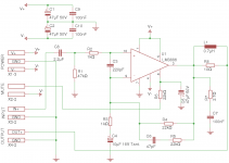
I Tried to attach Engel schismatic. Can you make pcb layout for this schismatic. is this circuit is correct.please help me.I don't want power supply on PCB. Error coming to post Eagle schismatic file. schismatic is same to my last post.
Thanks for your help.
Last edited:
What I was really proposing to do is get your eagle file and give you a few ideas so you could finally do the board yourself. passing eagle files back and forth . That way what you end up with will be much more rewarding for you
Hi availlyrics
I cant found same value input capacitor (C1) can you have any suggestion or equivalent for (C1). can i use any non electrolytic or electrolytic capacitor.please help me
Anything between .47 uF to 4.7uf (higher value = good bass)film type should work, stay away from electrolytic caps.
1.) Decide what frequencies you need to hear.
2.) Decide what frequencies the amplifier needs to pass to allow 1. to happen
3.) Determine the input filter RC time constant required to match 2.
4.) Select an input impedance and a capacitor value to match 3.
If the capacitor is below 10uF, then use a film capacitor.
If the capacitor is 10uF or above, then change the input impedance to a higher value.
- Status
- Not open for further replies.
- Home
- Amplifiers
- Chip Amps
- lm3886 single sided pcb