That's a good idea I'll try. It probably won't work because the DC-DC converter which powers the amp takes a *long* time to discharge and has an output pump capacitor that is very large (to handle the high loads)= 2200uf. Add 1000uf to each power rail of the LM3886 and you have a lot of capacitance for the poor MAX5486 to compete with 🙁
Your LM1875 biasing trick sounds interesting, but hard to follow without a schem.
I'm very happy with my single supply setup right now though, minus the pops. I wish I knew how to eliminate at least one and also know how the output caps are calculated (47000uf is a LOT). I'm using 2200uf right now at it seems good, but I would prefer to know how it's used, esp. if a high pass filter is involved (as with the LM4752).
Oh and I got 40v pumping out of the UC2577 (the LM2577 variant I'm using)! I measured 40v @1A on full loads and it came out to 20W per channel so efficiency must be really high (unless I measured something wrong). I'm going to make a switch for the UC2577 feedback though so I can run 25v still since the 40v output drains the battery heavily (even though it is high efficiency, it takes 4A+ to produce that load). The next thing I'm looking to add is a good preamp to boost the input signal since it is pretty low. When I used my PC audio as an external input (with the higher Vrms) I got much more output power.
Last edited:
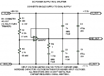
thanks for the schem gottee. that looks like a great circuit, how much current can it handle? It looks like you you used it for a low current application, but I'm wondering if I could get 40W+ out of it. If not I can use it for projects in the future though.
The low current across the resistors on the left is just for setting the output balance. The output current sources from/sinks to the rails via the power pins on the IC and is limited by the current capability and heatsinking of the IC. Cool design for applications where a floating ground is acceptable.
. . .The next thing I'm looking to add is a good preamp to boost the input signal since it is pretty low. When I used my PC audio as an external input (with the higher Vrms) I got much more output power.
Perhaps JRC4560 (a "stout" preamp), or JRC4580, or you might like a Jfet opamp chip instead. It seems that they are worth a try. And, howabout the "moosefet" project?
Aside from this, the only thing I have to contribute about a preamp is that you'll probably want to hold it steady by powering it from regulators.
thanks for the schem gottee. that looks like a great circuit, how much current can it handle? It looks like you you used it for a low current application, but I'm wondering if I could get 40W+ out of it. If not I can use it for projects in the future though.
The max current DEPENDS ON WHICH CHIPAMP IS USED. So do the max rail-to-rail voltage and the max power. If LM1875 is not enough, try LM3875, for example. Look at the datasheets for the specs and maximums.
You could also parallel two or more chipamps, to increase the max current and max power capability. You would just need to add a small resistance in series with each chipamp's output (say 0.1 Ohm), just before the point where the outputs all joined. You would want to keep a Zobel network for each chipamp's output
Last edited:
- Status
- Not open for further replies.