The LM3886 (LM4780) will easily drive a 2ohm load at +/-12V the only
problem is the voltage drop across the internal 0.45ohm emitter resistor
+ transistor junctions losses, but you will still have reasonable output
and fair to reasonable efficiency.
If you must use a single supply and where to go with BTL both amplifiers
settle to half supply Simultaneously so there is no turn on pop. The
problem with the LM3886 in the mute pin. If you use the LM3875 there are
only 5 active pins so it is very easy to use on a single supply,( I have
built a number of single supply LM3875 amps and a capacitor is required
for the half supply reference which affects the settling time and the
hole thing is not ideal)
Note the current limit for the LM3875 is only 6A. At least the emitter
resistors are still 0.45ohm.
Is it possible for you to split your 24V or do you have a single 24V
SLA?
I just tried my LM4780 BTL with only 2 12v SLA Batteries fully charged
at 13.8v (13.00 under load) and the output power was indeed 45w RMS
4ohm, Battery current was about 3.5A at 13V x2 = 91W so about 50%
efficient which is not too bad at all!
janneman- thank you for this explanation. The LM4752 actually pops when there is no audio signal in so it could be a similar issue since it is single supply. I will try a 1000uf and report back. On the 1k, do you mean this for Rm? I read somewhere here that a value too low on pin 8 will burn out the chip, do you think there is any risk of this?
VLSI-
thanks for the detail on your BTL setup. This sounds very promising, my only concern is if a parallel setup could be better (I'm willing to sacrifice the pop for lower heat and/or more output). The efficiency sounds promising and I would split the supply if I knew a good way to do it. The problem is I want to keep one battery so that I don't have to recharge them separately. Also, I am using a DC-DC converter (LM2577) so I can actually get a much higher output if needed. I configured it now to 29v output and could do more once I replace the caps (they are 35v tolerance now). Also, 6A is more than enough current limit since the LM2577 peak current is 3A anyway and my battery is 5A.
However, I don't know of a high-current high-voltage DC-DC converter inverter. I haven't poked around that much but it looks like most inverters max out at about 10W. If anyone knows a good chip to convert the 12v battery to -12v or lower with a high current output I would love to look into it because a dual supply would obviously be better. Splitting into 2 batteries is a no-go though because I would need protection circuit boards for both (it's a li-ion pack) and would have to charge them separately which would be a real pain and very impractical.
Last edited:
janneman- thank you for this explanation. The LM4752 actually pops when there is no audio signal in so it could be a similar issue since it is single supply. I will try a 1000uf and report back. On the 1k, do you mean this for Rm? I read somewhere here that a value too low on pin 8 will burn out the chip, do you think there is any risk of this?
[snip].
No, I said in series with the output capacitor. That slows down the charging of the output capacitor through the speaker, and will replace the pop with a slowly moving in and out and back of the speaker cone - please re-read what I wrote if you are not clear about this.
jd
I am not sure exactly what you are trying do achieve with your amp? How
much power? How long do you want your batteries to last? What is the
voltage of the battery you have ? is it from a laptop computer? How long
will the amp be in full or partial standby? If fact what is it for? It may be
that a class "D" or a Tripath class "T" is your best solution. Avoid
using a buck inverter as this will also add to your overall
inefficiency. and parallel class AB would be ok but the small increase
in efficiency will be totally outweighed by the inverter losses. Keen to
help and best of luck.
thanks for the clarifcation janneman.
VLSI, to answer your Qs:
What I would like to achieve with the amp is 10W+ per speaker (2ohm) or 20W+across them both (4ohm).
Battery last time: don't care really. If it's a high powered loud I'm happy with even 30min.
Battery voltage: I posted a schem on page one with the setup, it's a 12v 5A li-ion pack with a DC-DC converter upping it to 29v @3A.
When you say inverter loss on the parallel setup, do you mean it will lose output W?
The battery gets charged every day and it is used for a portable speaker system with two 6.5" Infinity speakers. I use it as a simple humble home audio system too (don't have the space, money, or interest in something more fancy.)
If I get 20W out of 2 LM3886s I will be happy. I am using an LM4752 now but greatly prefer the sound quality of the 3886.
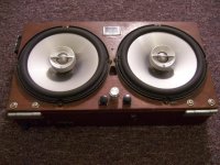
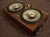
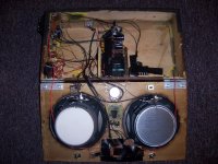
So I guess I'll try a bridge setup to go with your recommendation. Do you know of any single supply schems for this? and do I have to create an inverted signal for the audio line level inputs like I have seen in some schems (using opamps)? I'm afraid I am not too familiar with bridge and parallel amps. My major concern with a bridge setup is the heat, I've attached pics of my project and as you can see the heat sink and fan setup might not be adequate for that much heat. The LM3886 seems to run a lot hotter than the LM4752 at the same output load.
The inside shows a pic of the battery. It is essentially the same thing you would find in a laptop only in 12v config instead of the usual laptop standard 14.4v.
VLSI, to answer your Qs:
What I would like to achieve with the amp is 10W+ per speaker (2ohm) or 20W+across them both (4ohm).
Battery last time: don't care really. If it's a high powered loud I'm happy with even 30min.
Battery voltage: I posted a schem on page one with the setup, it's a 12v 5A li-ion pack with a DC-DC converter upping it to 29v @3A.
When you say inverter loss on the parallel setup, do you mean it will lose output W?
The battery gets charged every day and it is used for a portable speaker system with two 6.5" Infinity speakers. I use it as a simple humble home audio system too (don't have the space, money, or interest in something more fancy.)
If I get 20W out of 2 LM3886s I will be happy. I am using an LM4752 now but greatly prefer the sound quality of the 3886.
So I guess I'll try a bridge setup to go with your recommendation. Do you know of any single supply schems for this? and do I have to create an inverted signal for the audio line level inputs like I have seen in some schems (using opamps)? I'm afraid I am not too familiar with bridge and parallel amps. My major concern with a bridge setup is the heat, I've attached pics of my project and as you can see the heat sink and fan setup might not be adequate for that much heat. The LM3886 seems to run a lot hotter than the LM4752 at the same output load.
The inside shows a pic of the battery. It is essentially the same thing you would find in a laptop only in 12v config instead of the usual laptop standard 14.4v.
Attachments
Last edited:
Hi audiomodder
Tough project, and everything is such a trade off in electronics (and
life)
If fidelity and battery life are your priority try and incorporate a
second battery use a split supply and just run with the LM3886
If 12v is the priority take a close look at the Tripath IC's they are
tiny and efficient (up to 87%) but I think all the small Tripath IC's are stereo
and not sure about driving a 2ohm load.
But you are on the right track if you need both 12v and Hi Fi with a
buck boost PS.
If you are going to go to the trouble of a boost PS you may as well make
it a split supply and adjust you output voltage to suit you output
power needs.
For 20w into 4ohm +/- 15v will be fine, note if you increase your PS
voltage it will also decrease the overall efficiency if you then use
your amp at lower output powers.(another trade off)
As for battery life 20w out is about 40w DC in, less switch mode PS
efficiency (about 80%) so now 50w at 12v about 4A, maybe 45 min run time
on you 3A battery, But this should be longer as I assume it is for music
and speech.
Bias current and PS switching will flatten your batteries if the amp is
on with no input? (I think the LM3875 has about half the bias current?
The LM3875 is worth a try it is simple to use and was the chip in the
original Gain Card amp. Some DIY builders prefer it over the LM3886.
I have seen some great circuits at NS for split PS with there buck boost
chips.
Off cause you could probably do all this with a cheep stereo car sound
amp for a couple of $ at a recycle shop but I would not do that either.
Fun Project.
Kind Regards
BTW I realy like your wooden box! I am using wood on the front of the amps that I build.
I'm looking at some simple flyback/boost regs that might be used and came across this:
LM2588 - SIMPLE SWITCHER 5A Flyback Regulator with Shutdown
It says the NPN output can go up to 5A and it can produce - and + from a single 12v source with few components. But it says in flyback application the output current is internally limited to something fairly low. But I'm wondering if it's just for recommended use or if I can push something like +-24v @2A? The datasheet is not too clear and doesn't have any graphs for output load :/
If anyone knows if this would work I'd love to order it.
I also tested a higher cap for Cm and it didn't fix the pop...oh well.
I'm looking at some simple flyback/boost regs that might be used and came across this:
LM2588 - SIMPLE SWITCHER 5A Flyback Regulator with Shutdown
It says the NPN output can go up to 5A and it can produce - and + from a single 12v source with few components. But it says in flyback application the output current is internally limited to something fairly low. But I'm wondering if it's just for recommended use or if I can push something like +-24v @2A? The datasheet is not too clear and doesn't have any graphs for output load :/
If anyone knows if this would work I'd love to order it.
I also tested a higher cap for Cm and it didn't fix the pop...oh well.
Did you try the output series resistor?
jd
not yet, don't have a 1k with high enough wattage on hand. I think at this point I will just have to live with the popping since a series resistor on the output would get pretty hot I'm guessing and add even more weight to this heavy little box. It's just not worth it, but I can live with the popping.
If anyone knows if the LM2588 is up to the task I could just use that too and get rid of the pops that way.
If anyone knows if the LM2588 is up to the task I could just use that too and get rid of the pops that way.
not yet, don't have a 1k with high enough wattage on hand. I think at this point I will just have to live with the popping since a series resistor on the output would get pretty hot I'm guessing and add even more weight to this heavy little box. It's just not worth it, but I can live with the popping.
If anyone knows if the LM2588 is up to the task I could just use that too and get rid of the pops that way.
Both national.com and linear.com have completely-automatic power supply design tools, which will offer a choice of all of their applicable chips, given your specs. National's is on line and Linear's is in the File menu of their free LT-Spice simulation software. Both will automatically design a complete power supply after you select a chip to try. I recommend that you try both of them.
National's: Power Supply Design | National Semiconductor - WEBENCH® Power Designer Online Power Supply Design & Simulation Software Tool
Linear's: http://ltspice.linear.com/software/LTspiceIV.exe (right-click and Save Target As)
Both sites also have extensive collections of application notes and circuit designs.
Cheers,
Tom
Last edited:
If you end up stuck with one voltage, you can split the supply using an amplifier, such as a chipamp, by creating a virtual ground with its output. There is a simple schematic for such a "Split Power Supply" circuit shown in Figure 13, in the LM675 datasheet, at national.com . I imagine that the LM3875 might work well for that, in place of the LM675 in the schematic. I have used the LM1875 with that circuit, with very good results. The current and voltage handling capabilities basically depend only on the amplifier used.
LM 675 is just what I needed...I was looking for a split power supply for making a small subwoofer for my car.. but do you have any idea what are the power dissipation ratings for the resistors in the split supply application
power dissipation in the charge up resistor is not a problemnot yet, don't have a 1k with high enough wattage on hand.
12.5V gives just 156mW (12.5*12.5/1000) for the first few us and falls exponentially to zero mW over a few seconds. It will not even get warm.
BTW,
how do you charge the battery? From the mains? Why can't you use the battery charger as your supply?
Andrew, watts...unless I am misunderstanding something I would need at least a 5W resistor like the ones used in the bridge setup. Also I cannot use the battery charger as a supply...that would kill the idea of this being a portable setup and I don't have a good enough mains either. It's a 500mah max charger taken from modded product. It's a very small 14v transformer. I want to avoid building/buying a large transformer to produce the voltages like most people do...it's too heavy, expensive, etc. among many other reasons. I'm not using wall transformers for this project.
Update on the project: I've installed both LM3886s into the enclosure and am playing them now...and they sound great!! A nice little improvement from the LM4752, especially since they have much lower distortion on the bass-heavy loads. The heat is completely managable at +29v right now as the fan cools both chips significantly with the small heat sink. I've noticed my MP3 player could really use a preamp to boost the volume too, and could make for a much better output. It's operating on only 1.2v right now so I think that accounts for the low signal going to the amp.
Gotee: That LM675 looks great. How well-regulated is the output from your experience? I really like the fact that it doesn't need a transformer. The graph on the output limit is a bit confusing on page 3 (current limit vs. output voltage) since it has an asterisk noting Vs @ +-25v. I can only guess that this graph does not apply to the single to split voltage schem?? According to national's website design software this has a very limited current output too. But I don't trust their specs necessarily since the LM2577 has very limited output and yet I'm pumping way more power from it that it is supposed to handle. I did the search as suggested but nothing came up except for the LM3488 which is a) expensive and b) in a very inconvenient package (SO8) for heatsinking. If anyone knows how to get samples from national without paying an arm and a leg for shipping I'd love to know..
Also the LM675 can only split the supply once it is stepped up, which means efficiency issues I'm sure. I would be using an LM2577/2588/3488 to step up to 40v ideally and then split it. and I wonder is just cutting out the LM675 and using a single supply is nearly the same output power without all the hassle. I'm sure it sounds better on a dual supply but how much can the difference really be? Maybe I'll build a test circuit later to judge the difference by ear myself.
I'm going to try upping the voltage to 40v @ 3A single supply once I get my new caps. I'm crossing my fingers in hopes that it won't just smoke the LM2577 at that power.. if this works I think I will have more than enough power with the heat being managed and I will be done with this part of the project I think.
I'm also using only 1000uf for the output caps right now and it seems fine. I really wish I knew the reasoning behind the 4700uf in the schem though. That and the popping are the only downsides but they're not bad. This chip sounds fantastic.
the charge up resistor sees half the supply voltage across it when the output cap has zero volts.I am misunderstanding something I would need at least a 5W resistor like the ones used in the bridge setup.
The output cap charges up to half supply voltage and then the resistor has zero volts across it.
This charge up takes just a few seconds. After this short time the relay shorts across the charge up resistor and the speaker current passes through the relay contacts.
At start up the power dissipation of the charge up resistor is voltage squared divided by the resistor value.
12.5V gives just 156mW (12.5*12.5/1000) for the first few us (micro seconds)
LM 675 is just what I needed...I was looking for a split power supply for making a small subwoofer for my car.. but do you have any idea what are the power dissipation ratings for the resistors in the split supply application
It wouldn't be much. For the two 47K resistors that divide the input, using Ohm's Law, Voltage = Current times Resistance (or, equivalently, Current = Voltage divided by Resistance) and ignoring the miniscule current into the amplifier's input pin, the current through them would be I = Vin/(2xR). If Vin were even, say, 70V, the current would be only 70/(2x47000) = 0.745 mA.
The power dissipated would be voltage times current, or, equivalently, voltage squared (voltage times voltage) divided by resistance, or, equivalently, current squared times resistance. For 70V input that comes out to 0.026 Watt, or 26 milliWatts (mW).
For the 1 Ohm in the Zobel network on the output, I'm not sure. It should be very low, too. But it might depend on what you are powering, somewhat.
I actually modified that circuit, to give what I think is better performance (although "your mileage may vary"): I added a 1KOhm (1000 Ohms) resistor from the point between the two 47K resistors to the amp's negative input pin (still keeping the wire from that point to the amp's positive input pin), and changed the two 47K resistors to 22K each, and changed the top 22K resistor to a 16K resistor in series with a 10K ten-turn trimpot (so I could adjust it to get exactly-equal + and - output voltages), and changed the feedback (from amp output to negative input) to be 15K Ohms in parallel with 100 picofarads (pF) instead of a wire. I also increased the ouput smoothing capacitors' values to something like 2200 uF each. In one version, I also added a zobel-like 100 Ohms in series with 22 uF, in parallel with the lower 22K input resistor, and a 0.1uF in parallel also. I did not use the LM675, either, using an LM1875 instead. But other amps or chipamps could be used there, depending on your voltage and current requirements.
Happy New Year,
Tom
Last edited:
the charge up resistor sees half the supply voltage across it when the output cap has zero volts.
The output cap charges up to half supply voltage and then the resistor has zero volts across it.
This charge up takes just a few seconds. After this short time the relay shorts across the charge up resistor and the speaker current passes through the relay contacts.
At start up the power dissipation of the charge up resistor is voltage squared divided by the resistor value.
And, we should state, most resistors can dissipate far more than their power rating, for a short time, without any problem.
my post above got cut off somehow...what I was saying was that he meant a resistor in series with the output....not Rm, so if I am not mistaken this should need to be a high watt resistor since the output is high wattage...I don't believe this is a charge up resistor.
gootee, do you know how much power (watts) got out of your LM675? That would be good to know, if you would be willing to just post your input voltage and amperage and the same for output.
Also, I'm getting a power down pop from my LM3886 now that it is installed in my enclosure. This is probably because of the MAX5486 digital pot I'm using. When I turn off the system the MAX5486 goes off first (since there aren't huge caps on the power line for that guy) and so the LM3886s don't see an input signal and thus the pop.... anyone know a good way around this? I can deal with the start on pop but the off one too...that's really frustrating.
my post above got cut off somehow...what I was saying was that he meant a resistor in series with the output....not Rm, so if I am not mistaken this should need to be a high watt resistor since the output is high wattage...I don't believe this is a charge up resistor.
gootee, do you know how much power (watts) got out of your LM675? That would be good to know, if you would be willing to just post your input voltage and amperage and the same for output.
Also, I'm getting a power down pop from my LM3886 now that it is installed in my enclosure. This is probably because of the MAX5486 digital pot I'm using. When I turn off the system the MAX5486 goes off first (since there aren't huge caps on the power line for that guy) and so the LM3886s don't see an input signal and thus the pop.... anyone know a good way around this? I can deal with the start on pop but the off one too...that's really frustrating.
There was no LM675. I used an LM1875T.
Almost all of the work is done by the upstream power supply.
My power supply splitter was used in an instrumentation product (a small Curve Tracer) and I don't remember the power numbers for it. But I have a simulation that I used for it, at the time, in front of me now. I put 35 Volts across the LM1875T's power pins, and split it into +/-17.5 Volts, with the LM1875T's output becoming the new virtual ground for everything downstream.
In the simulation I have just run with that, there are 25 Ohm load resistors on each 17.5V rail (+ and -), to the new virtual ground at the LM1875T's output. (I actually am using an OPA541E chipamp model, for simulation, instead of LM1875T. But that shouldn't matter.) In addition to the two 25 Ohm resistor loads, there is a chipamp across the + and - rails, pumping +/-15V (relative to virtual gnd) square waves into a 10 Ohm resistor connected between its output and virtual gnd. There's also an LM1086-5 5V regulator between the +17.5V rail and the virtual gnd, with a 200 Ohm load resistor. Altogether, over 39 Watts are being dissipated, not counting the chipamp acting as the power supply splitter.
The "rail splitter" chipamp itself was dissipating about 0.892 Watts. The current into the chipamp's V+ pin was about 33.27 mA RMS, and V- pin's current was about 19.77 mA RMS. The output pin's current was about 17.5 mA RMS (and -11.78 mA average).
<snipped>
Also, I'm getting a power down pop from my LM3886 now that it is installed in my enclosure. This is probably because of the MAX5486 digital pot I'm using. When I turn off the system the MAX5486 goes off first (since there aren't huge caps on the power line for that guy) and so the LM3886s don't see an input signal and thus the pop.... anyone know a good way around this? I can deal with the start on pop but the off one too...that's really frustrating.
Maybe you could just use a larger cap for your digital pot than for your amp, or use the same size as for your amp but with a larger bleeder-resistance, so it goes off last. Would that cause any problem at start-up?
It sounds like what you really need is a startup and shutdown control circuit for the mute pin, or for a speaker relay.
Last edited:
- Status
- Not open for further replies.
- Home
- Amplifiers
- Chip Amps
- LM3886 silent? (Ive searched many threads for a fix)