hey all,
I know there is a bazillion topics on this chip but I've searched through dozens and dozens of threads and web pages and cannot find a fix for mine. There is *very* little info on the single supply setup which is what I am working with.
I attached the schematic I built, which is the same as the official application minus the optional components. However, I do not understand the Rm equation very well since I am not using VEE...I've tried 10k and 22k values but nothing works. I'm using a 24v power supply.
The base of the transistor has a 12v bias (which I also read on pin 10), the output (pin 3) reads 23v. But all I get is a loud pop when I power it up and no sound at all. Any ideas?
Attachments
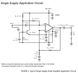
You do know that Ci is not optional in a single supply application despite the asterisk next to it? (Omitting it will result in a dc gain of 21 instead of unity, and the output stage will slam to the positive rail.) Hope this is the issue with yours. I've used these in a number of applications with bi-polar supplies and have found them to be pretty trouble free..
Last edited:
For single ended operation Rm<(V7-2.6)/I8 where V7 is the voltage at pin 7. I8 is 0.5 mA or more. For your example V7 is about 11.5 and if we choose 1 mA for I8 then Rm is 8.9K. Since I8 can be as small as 0.5mA, Rm=10K should work. Cm creates a time delay and for now I would remove it until your problem is sorted.
I don't understand your DC voltage readings. Pins 3, 9, and 10 should all be the same, around 12 volts. It might be worthwhile to measure the DC voltage at all the pins and post the results here.
I don't understand your DC voltage readings. Pins 3, 9, and 10 should all be the same, around 12 volts. It might be worthwhile to measure the DC voltage at all the pins and post the results here.
Thanks for the quick replies! I am using a 10k from pin 8 to pin 4 without Cm. Thanks for the info on Ci, it looked necessary so I included it (weird they have that asterisk there) Here are the voltage readouts I am getting:
1- 24v
3- 23v
5- do I connect Vin here?
7- 12v
8- 0v
9- 23v
10- 12v
good to know I'm looking for 12v on pins 3 and 9...I wonder why they're different? Maybe the chip is blown 🙁
Also the schem doesn't show pin 5 but in the first schem on the data sheet its connected to Vin...I tried this but got the same results.
Last edited:
Besides pins 3 and 9 being the wrong voltage, pin 8 should be around 9 volts, not 0. Unless there is a wiring error, the chip may be blown. Turn the amp off and try measuring the resistance from pin 3 to pin 1 and then from pin 8 to pin 4. If either or both readings are near zero the chip is probably bad.
You can connect pin 5 to Vin but the datasheet indicates pins 1 and 5 are both Vin. From that it seems either or both pins connected to Vin is ok.
Ci is an optional component only for + and - supplies, not for a single supply. It should not be listed as an optional component for a single supply application.
So I checked for shorts and there weren't any however, I desoldered the entire chip and just tried plugging in the supply voltage and behold- 23v on pin 3. So it would short but only on startup.
Fortunately I have another LM3886 here that I swapped in-- and it works! and boy does it sounds great... only one small problem and that is that is the output seems far below what it should be...is there any way to adjust the gain or is the output for a single 25v just really low?
Thanks for all your help!
The gain is 1+Rf1/Ri which is 21. You can reduce Ri to raise gain but maybe the real problem is your input voltage is low.
With Vin at 24 volts you will only get 5 watts or so output, depending on the load impedance. If your speakers are not efficient that will not drive them very loud.
With Vin at 24 volts you will only get 5 watts or so output, depending on the load impedance. If your speakers are not efficient that will not drive them very loud.
I tried reducing Ri to 680ohms but then the bass section began to get distorted...
Only 5 watts output though?? I thought this amp could pump out a lot more than that, even at low voltages....I was looking to replace my LM4752 which does 11W per channel on a 24v supply.
Unless there is a way of reducing the distortion on higher gains this sucks 🙁
Very nice sounding chip but maybe it is only for really high volt apps :/ Maybe I'm dreaming too big with my 12v battery converted to 24v 3A output.
Increasing Ci will bring some of the bass back. I'm not familiar with the LM4752 - maybe I will get some time to look it up tomorrow.
Thanks for the Ci tip, that seemed to help. The LM4752 is really an interesting one, single supply only though, but I've enjoyed it for quite some time because it sounds very nice. The 3886 is better though, and if I can get 2 of them into my setup and the gain adjusted better I'll drop my LM4752. Is there no way to get more power out of it at 24v?
Last edited:
With a 24V supply a single chip amplifier can theoretically output 9 Watts into 8 Ohms. That's if the chip is lossless which is not possible. The LM4752 is rated at 7 Watts at 10% distortion into 8 Ohms with a 24V supply. The LM3886 is 5 or 6 watts at 0.1% distortion into 8 Ohms with a 24V supply. This is taken from a graph in the datasheet and this data point is way at the bottom of the curve so it's hard to be precise about the power number. Note also the big difference in the distortion rating. I think both amps put out about the same power at 24V.
You will be much better off to build a power supply that puts out +/-35V which allows the chip to put out about 40 Watts. The dual supply also may allow you to remove Q1, the input cap, Ci, and the output cap. It should also sound much better.
You will be much better off to build a power supply that puts out +/-35V which allows the chip to put out about 40 Watts. The dual supply also may allow you to remove Q1, the input cap, Ci, and the output cap. It should also sound much better.
Yeah, I looked at that graph after you mentioned the 5W output and I see what you mean. The output seems a little lower than the LM4752 (even with distortion considerations) but not by much. However, I did manage to safely (so far) boost the supply voltage to 29v which gives a nice extra amount of output (the graph shows a significant difference between +-12 and +-15v).
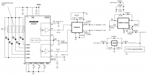
My setup is a bit unique though (and inefficient in some ways) since I am building a hifi portable amplifier. Thus the single supply and low voltage limitations. I attached a schem of the major parts of the design. The battery is ~12v @ 5amps
I am actually using 2ohm speakers (x2) which is not the best for the LM3886 from what I have read but is still nice. I would series them but I would like to use 2x LM3886 for better output. I am a little bit worried about how hot the chip gets but I do have a 2" X 2" finned heatsink with a fairly powerful cooling fan that could possibly do the job. I also noticed it can handle a LOT of heat before the distortion kicks in and I couldn't even reach a thermal shutdown running it on a tiny heatsink.
Theoretically I could upgrade the caps on my LM2577 and the amps to 50v tolerance and produce a higher output voltage. However, 2x LM3886 @ 29v input is giving me enough power I think for right now (assuming they don't get too hot).
My only questions now are:
1) how can I reduce the start-on popping when no audio source is connected? (added a 100uf cap from pin 8 to pin 4 and tried a 150uf but it still pops). I wired a 10k resistor from pin 8 to 4 because I don't want to use the mute feature.
2) given my lower voltage input, could a smaller output cap work to replace the 4700uf value? I'd much rather use 1000uf but I'm wondering if this will effect the filter frequency too much.
3) I want to make sure I am calculating Ci correctly. The equation:
fc= 1/(2*3.14*Ri*Ci) for the schematic in the datasheet this comes out to:
fc= 1/(2*3.14*1000*0.00001) = 15.9? So that's the highpass frequency? Seems a bit low if that is correct. I'd like to make this higher to match my speakers which can only go down to 45hz.
4) Rsn and Csn added a *lot* of extra noise on the output...I'm wondering if I should just not add the optional components? It sounds great the way I made it in the schematic above, can anyone recommend adding some of these other parts for a significant quality increase?
5) I am also considering using a bridged LM3886 setup like the one over here: http://www.dckits.com/app3.htm anyone know of more good info/threads that discuss this? This could solve the heat problems perhaps and deliver more output to both speakers which could be connected in series to make a 4ohm load.
Thanks for all the help-
Attachments
Last edited:
. . .
I am actually using 2ohm speakers (x2) which is not the best for the LM3886 from what I have read but is still nice. . . .
needs paralleled pair of 4 ohm stable amplifiers per each 2 ohm speaker
Can stop the popping by using the mute feature, causing the resistor that goes to mute to also charge up a cap (time delay).
If you have 8 ohm speakers, try bridged LM1875's.
LM1875 is an older chip with more distortion and the same output power if not less than the LM4752 or 2x LM3886.
Can stop the popping by using the mute feature, causing the resistor that goes to mute to also charge up a cap (time delay).
I already added the resistor and the cap (between pins 4 and 8) as written in the schematic. This did not stop the startup pop. It is softer when I apply an audio signal before startup though.
It also works fine with the 2ohm load especially given the low power output. The LM4752 is not designed for 2ohm loads either but has been working great with these speakers.
bridge
Hi audiomodder
Hi audiomodder
I have not read all of this thread but I think your best solution is a
bridge configuration, I am currently working on a bridged LM4780 (eqiv
2xLM3886) and with +/-24v from 4x 7A SLA Batteries the output power is
100W RMS 8ohm. with +/=12v you should be able to achieve 25W RMS 8ohm
and about 45W RMS 4ohm.
Although this equates to a 2ohm load for each chip at 12V this is 6A
peak well below the 11.5A output current limit for this chip. Limiting
factors include the Clipping Voltage vs Supply Voltage (see page 12
LM4780)
Note. if you bride a single ended amplifier as both amps outputs are at
half supply, the net DC at the speaker is 0V so no need for output
capacitors (this is the configuration for all cheep car stereo
amplifiers)
Just follow the applications notes and if you have any instability
issues try a 47pf mica capacitor between the + and - inputs on each
chip at the chip. Also a 220pf capacitor across the input after a 150R resistor with help filter unwanted HF noise.
If you would like to look at the single sided PCB I designed and made.
http://www.diyaudio.com/forums/chip-amps/79303-chip-amp-photo-gallery-25.html (top of the page)
I used it in parallel mode for this amp.
Hi audiomodder
Hi audiomodder
I have not read all of this thread but I think your best solution is a
bridge configuration, I am currently working on a bridged LM4780 (eqiv
2xLM3886) and with +/-24v from 4x 7A SLA Batteries the output power is
100W RMS 8ohm. with +/=12v you should be able to achieve 25W RMS 8ohm
and about 45W RMS 4ohm.
Although this equates to a 2ohm load for each chip at 12V this is 6A
peak well below the 11.5A output current limit for this chip. Limiting
factors include the Clipping Voltage vs Supply Voltage (see page 12
LM4780)
Note. if you bride a single ended amplifier as both amps outputs are at
half supply, the net DC at the speaker is 0V so no need for output
capacitors (this is the configuration for all cheep car stereo
amplifiers)
Just follow the applications notes and if you have any instability
issues try a 47pf mica capacitor between the + and - inputs on each
chip at the chip. Also a 220pf capacitor across the input after a 150R resistor with help filter unwanted HF noise.
If you would like to look at the single sided PCB I designed and made.
http://www.diyaudio.com/forums/chip-amps/79303-chip-amp-photo-gallery-25.html (top of the page)
I used it in parallel mode for this amp.
The LM3886 has two pins for V+; pin 1 and pin 5. Your schematic only shows one of them connected. Make sure to connect both to your 25 V supply.
Rm should be calculated to give a current in the mute pin of approx 500 uA. Looking at the equivalent circuit diagram on page 7 of the data sheet, it can be deduced that the voltage of the mute pin will sit -3*Vbe below your ground reference (pin 7 - 12 V in your case). 3*Vbe = 2 V (approx). So (10 V)/(500 uA) is your max Rm --> Max Rm = 20 kOhm. Your 10 kOhm should be fine but there's no need to go lower. Cm ensures that the mute is disabled slowly after the power supply powers up. It's probably not strictly needed, but I would definitely use it. That 10-cent cap will greatly reduce any turn-on pops. In fact, I'm using the LM3886 in an amp right now and have NO turn-on pops at all.
Your original issue was probably not caused by the lack of Cm. That sounded more like a shorted output stage to me. Wonder how that happened...
~Tom
tomchr- I fixed the mute startup issue with the 10k but it's the popping that I am trying to fix now. Even with Cm it pops very loudly, especially when I don't have an input audio signal connected. You say yours doesn't pop, do you have any ides why mine is? Is yours pop-free even without an audio signal connected on startup?
The original issue was a shorted output stage. I'm sure it happened through my own error in building the circuit some years back, I was reusing the same chip instead of buying a new one (to save on cost).
VLSI:
It actually sounds like a parallel circuit might be better with my setup but I'm not sure. I'm just learning now about parallel and bridging amps. I've been reading over here about it:DC Electronics - Kits
and this stuck out to me:
"Remember that in a BTL (bridged) configuration each amp only sees half the load impedance, so using a BTL pair to drive a 4 ohm load should be avoided. The same pair will, however, do a fine job driving an 8 ohm load. Operating 2 or more LM3886s in parallel gives increased output current capability, but more importantly makes it easier to deal with thermal issues."
so bridged on 4ohms is supposed to be not so good I guess. and I really would like the chips to run cooler since I think my heatsink won't be adequate for a lot of heat from both chips. I haven't been able to find a single supply parallel circuit though and I'm concerned that there might be issues trying to apply this to the single supply setup (it would be nice to know that someone has tried it successfully before).
If anyone can help answer my questions from post #14 that would be a good help.
thanks everyone for the speedy input.
[snip]If anyone can help answer my questions from post #14 that would be a good help.
thanks everyone for the speedy input.
If I understand correctly, you're using a single supply with a capacitive output to the speaker? In that case, I think you *always* will have a pop.
As soon as the amp is switches on, the output needs to rise to mid-supply, charging the output cap to mid supply. That charge current, which basically is a one-time pulse, runs through your speaker. Hence the plop.
The only thing you can hope for is to extend that charge pulse so that it has only lf components; in that case, you will not hear a plop but will see the speaker cone slowly move in and out back to mid position (or reverse).
Try a really large mute cap like 1000uF, see if that lowers the plop freq to inaudible. (Edit: It may not work well as the mute characteristic is probably not completely linear; I didn't check the data sheet).
Edit: a drastic measure would be a large series resistance like 1k with the output capacitor, that is shorted out by a timer after say 10 seconds after switch-on. You could try that by hand to see if it would work.
jd
Last edited:
- Status
- Not open for further replies.
- Home
- Amplifiers
- Chip Amps
- LM3886 silent? (Ive searched many threads for a fix)