
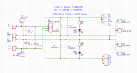
I frequently deploy a C+RC snubber across each transformer secondary, where Cx=Cacross is implemented as an MOV (metal oxide varistor) instead of a capacitor. The MOV (a) is about the same cost; (b) can be Quasimodo-optimized for critical damping just like a capacitor, and (c) adds an extra layer of surge protection, for free. To see one example, search the Forums for threads with "VRDN" in the title.
Will something like this work? - https://www.mouser.com/ProductDetail/Bourns/MOV-07D470K?qs=lgttKnAd%2B2DrMJUU5I413w==
I am assuming I would use two of them - one for each transformer secondary coil - those are 25V AC each.

Just finished building my LM3886 amp and used only 10,000uF per channel for the power supply filtering. Guess what, the voltage without load is 62V, but with the load, the voltage dips to 58V! It looks like adding more of the capacitance is essential.

CRC? Like a filter?Could you do an add with the CRC and fuse holders? It wouldn't go amiss...
Could you do an add with the CRC and fuse holders? It wouldn't go amiss...
Here is the thread where I simulated multiple scenarios in the LTspice. I don't think that CRC filtering is the best way to go for the power supply - https://www.diyaudio.com/community/...us-crc-filter-simulation.386838/#post-7037446
Law of diminishing returns. No resistor and four 10,000uF caps gets you variation of 1V. Add two 0.22R resistors (CRC filter) and the variation is in the range of 0.65V. Adding four 0.22R resistors (RCRC) reduces variation to 0.55V. Not worth it in my opinion.

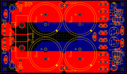
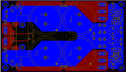
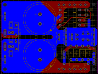
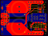
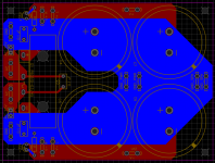
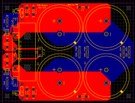
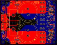
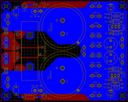
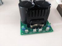
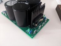
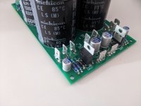
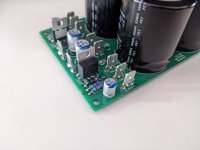
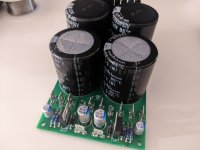
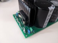
Photo dump of assembled psu board:
Attachments
-
 PXL_20220704_223620356.jpg220.9 KB · Views: 166
 -
 PXL_20220704_223623737.jpg235.9 KB · Views: 153
 -
 PXL_20220704_223637921.jpg314.2 KB · Views: 158
 -
 PXL_20220704_223642925.jpg268.1 KB · Views: 162
 -
 PXL_20220704_223608997.jpg284 KB · Views: 153
 -
 PXL_20220704_223615395.jpg244.4 KB · Views: 158
 -
 PXL_20220704_223629785.jpg249.1 KB · Views: 153
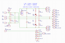
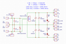
FIXED MAJOR MISTAKE IN THE LAYOUT!!!
Pinout of the LM337 in TO-220 package is not the same as with LM317!
Pin 1 is ADJ for both LM317 and LM337
Pin 2 is IN for LM337
Pin 3 is OUT for LM337
Pin 2 is OUT for LM317
Pin 3 is IN for LM317
Attached are the schematics and gerbers with the correct layout.
Pinout of the LM337 in TO-220 package is not the same as with LM317!
Pin 1 is ADJ for both LM317 and LM337
Pin 2 is IN for LM337
Pin 3 is OUT for LM337
Pin 2 is OUT for LM317
Pin 3 is IN for LM317
Attached are the schematics and gerbers with the correct layout.
Attachments
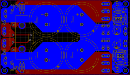
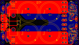
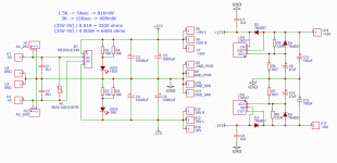
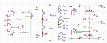
Revisiting this thread as I am creating new design layout in KiCAD now. Schematics attached reflects all of the components that might be placed but could be omitted. Main filter caps are 6800uF and are 25mm in diameter. Makes for a nice compact PSU board.
Attachments

- Home
- Amplifiers
- Power Supplies
- LM3886 power supply