If you can do a small test: Connect the transformer to a rectifier bridge and to two buffer capacitors. Draw 100mA from each buffer capacitor and measure the two buffer capacitor voltages. Then, we can better tell you what to do.
Eventually, use the rectifier and the buffer capacitors from the Pioneer for this test.
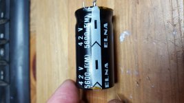
Hi thanks. so i performed the test you suggested using the 2x 5600uf 42v caps from the pioneer and a 330ohm resistor as load. and i got -44.7 +44.7.
Hi thanks for the help. I set up the circuit you suggested but i'm unsure of how to draw 100ma from the caps can you help further pls?
Yep, 10 times (in Ohm) the voltage (in Volt) you have across each capacitor (probably 10x43V= 430 Ohm); 10W if you have.
Hi thanks. so i performed the test you suggested using the 2x 5600uf 42v caps from the pioneer and a 330ohm resistor as load. and i got -44.7 +44.7.
Good work, but is it true that the Pioneer transformer, with the Pioneer 5600uF capacitors leave a voltage on the capacitors (44.7V) that exceeds the rating of the capacitors (42V)?
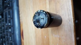
Yes I was a little confused about that myself would the bridge rectifier make a difference as i use one i already had setup?. Something else i was a little confused about is the caps have 3 pins.
Would it be possible to post us a photo of these 3 pins? I have seen such in an old Marantz amplifier where the capacitor was a double 2x13000uF type. They are rare.
One rectifier should give close to the same voltage as another.
Scott seems to have spotted to reason for three pins: Avoid symmetry so you cannot turn them wrong in production. Simple and smart. I found some from Vishay.
Sorry for the break. A mini laptop with a French keyboard layout is not easy to work on.
The 44.7 V is clearly too much and in excess of what can reasonably be dropped off by extra rectifier diodes. In my following posting I will try to list the options you have if you want to use this transformer.
This posting I forward now so you know I haven't just gone to bed. FR is ahead of UK time-wise.
The options I see:
1) remove some secondary windings. It requires you can get to the secondary windings and that the secondary windings are wound "bifilar" such that you remove windings from both secondaries at the same time. If, the secondary windings are hidden behind a primary winding, if one secondary winding is on top of the other secondary winding or if the transformer windings are covered by a wide copper band (mine are) at the outside of the windings, this option is not feasible. This idea was proposed by MAAC0.
2) Use of a pre-transformer (a "bucking transformer") which, operating as an auto-transformer, reduces the input voltage to your 30-0-30 transformer. This good idea came from "00940" in Liege/Luik and (he/she) even made calculation for what you need. This solution requires an extra transformer but smaller than your 30-0-30 transformer.
3) Use of a parallel transformer. This idea is based on letting two transformers operate in parallel but in counter-phase such that a small transformer subtracts a part of the secondary voltage of the main transformer. The small transformer has to carry the secondary current of the main transformer. And, the small transformer needs to have two separate secondary windings (not with a center tap). Something like a 230V/2x6V-50VA transformer is useful. Again, you need a second transformer for this solution.
4) A voltage dropper circuit, thus, a regulated or fixed linear series element reducing the 44.7V input voltage to more or less what you like (easy to adapt). The clear disadvantage is the power loss in the linear series element (two elements for symmetrical voltages) and you need to do some breadboarding (this was why I asked about your experience with vero-boards). In this case, you probably end up making the power supply board yourself because symmetrical linear power regulators that can handle +/-50V input and supply some 5A at the outputs are difficult to find as kits or ready-made boards.
5) And, then the trivial solution: Get another transformer. I also like not to spend much on transformers (in particular freight). I find old amplifiers/receivers at dump-yards or sold as defect by private persons. From the specification sheets I can normally get a quite good idea about the transformer voltage and capacity before buying. You should look for 2x22V/200VA, hence, an amplifier that is designed to operate with 4 Ohm speakers.
Do any of these options appeal to you?
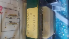
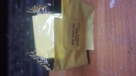
Hi I have 2 smaller transformers 1from a computer psu. And 1 from a large ghetto blaster type stereo. Can post pics if that helps.Really the best thing is to have the right size transformer in the first place. What other ones have you, what did they come out of?
Hi options 2 and 3 look attractive as I have a few transformers 1 may do the job the problem I have is I don't know the ratings of them as I got the from other salvaged items.Do any of these options appeal to you?
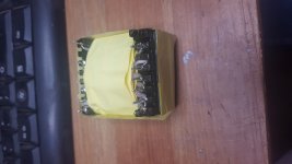
The computer psu transformer is, unless it is very, very old, from an SMPS. Thus, useless for this purpose. The ghetto blaster transformer could be useful. I assume it has a 230V input? Can you see what are the output voltages from secondary windings? Perhaps it could be used as a pre-transformer for the 30-0-30 transformer.
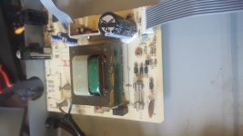
Let me know if you need more.Could you make us a photo of the ghetto blaster transformer and the Pioneer tuner transformer (without dismantling the tuner yet, just remove the top cover)?
Attachments
- Status
- This old topic is closed. If you want to reopen this topic, contact a moderator using the "Report Post" button.
- Home
- Amplifiers
- Power Supplies
- LM3886 power supply