Hi Tomchr, thanks for posting your measurements. I had talked myself into believing that a small amount of inductance in the lower part of the feedback loop was a good thing. My reasoning was that it would reduce the gain at HF (in the same way that Ci reduces the gain at DC) and that this would increase stability.
If you want lower gain at HF, a cap across the feedback resistor is a better option. That sets up a pole-zero pair in the loop, though. Sometimes that's what you want, but if not designed in carefully, you can totally trash the phase margin of your amplifier, turning it into a power oscillator. Trust me. It's not pretty when that happens... 🙂 An LM3886 will merrily oscillate at a few MHz if you force it that direction.
Note that this is usually not an issue for regular LM3886 builds. Just build it according to the Typical Application schematic shown in the data sheet. Add the "optional stability components" shown in the AC Test Circuit in the schematic, and you're good to go. Don't forget the decoupling caps. Oh ... and do a good job on the layout. 🙂
Tom
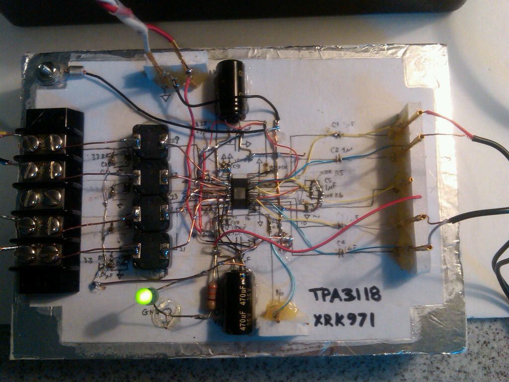
Here is a Macgyver style class D TPA3118D2 chip amp with p-t-p wiring using SMT components. This was before cheap Chinese TPA boards were available. I never measured THD but it sounds good - almost as good as a PCB board probably. There is a layer of grounded aluminum foil glued under the white paper for a ground plane.
http://www.diyaudio.com/forums/class-d/219730-tpa3118d2-6.html
Closeup:
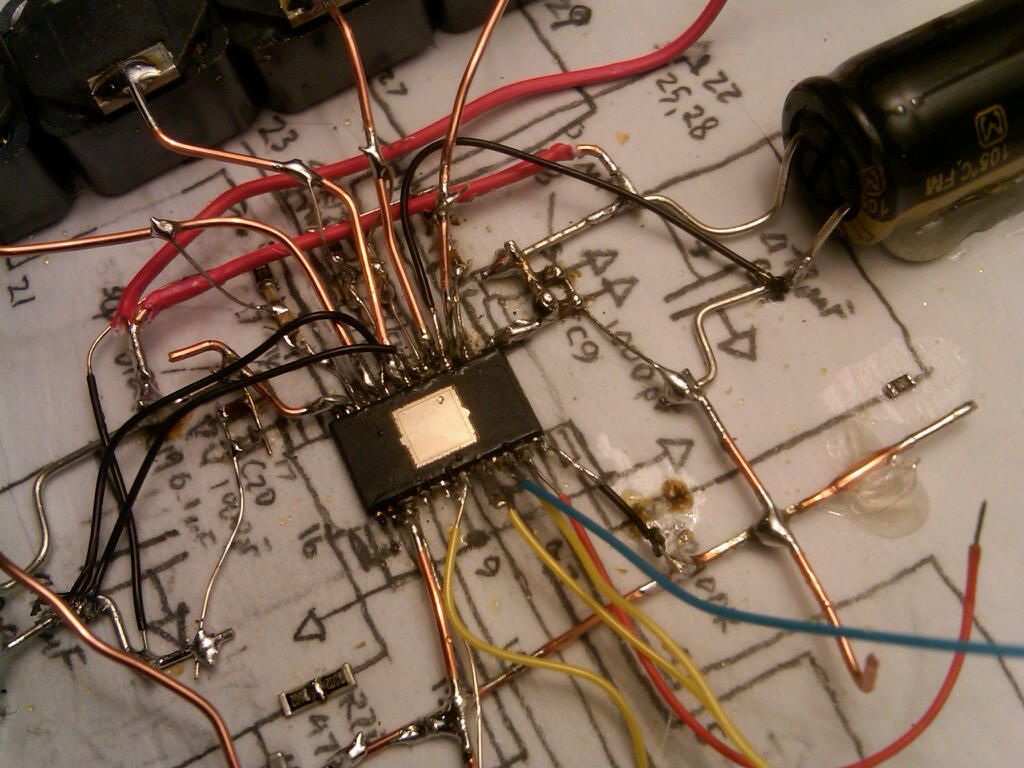
That was fun, sort of... 🙂
http://www.diyaudio.com/forums/class-d/219730-tpa3118d2-6.html
Closeup:
That was fun, sort of... 🙂
Unfortunately this conclusion is contradicted by measurement. 60nH is 7.5mΩ at 20kHz and, as you noted, 20kHz THD increases by 10dB when it's inserted.I find it doubtful that the addition of a few 10s of mΩ to R1 will cause the rise in THD. That sounds like hand-waiving to me.
I do share the skepticism but for different reasons. The 20kHz errors here are about -95dB and 95dB down from the 261Ω feedback resistor is 4.6mΩ. So the quantities are of the right size. What's missing is a plausible mechanism by which an increase in a linear layout parasitic results in this level of nonlinear behaviour. However, the mechanisms I'm aware of should result in terms 120-140dB down.
If 35W 8Ω is at the edge of clipping it may be interesting to have a look at lower power. Occam's razor suggests the parasitic is nonlinear, though.
Seriously?? You're going to question someone's engineering credentials because of a soldering iron slip that is of no consequence? Apparently you're totally immune to mere human mistakes...it must be AWESOME being you!
Mike
Mike
Here is a Macgyver style class D TPA3118D2 chip amp with p-t-p wiring using SMT components.
That was fun, sort of... 🙂
Words fail me. That is an epically awesome P2P build. You clearly have more patience than I do. It would be interesting to "sniff" around that amp with an inductive pickup probe on a spectrum analyzer.
No, just the opposite, the best engineer I know can't solder half that well.
Thanks. I've been at it for a while. I've been soldering longer than I've been able to write. Got my first own soldering iron when I was in first grade because my dad was tired of me always using his soldering iron. Not that he ever used it, but whatever... 🙂
I interpreted your original comment as sarcasm, by the way. No harm done.
Tom
No, just the opposite, the best engineer I know can't solder half that well.
OK, I guess I missed the sarcasm. Sometimes it's hard to sort out the snark from the insults. Apologies for misunderstanding the intent.
Mike
Words fail me. That is an epically awesome P2P build. You clearly have more patience than I do. It would be interesting to "sniff" around that amp with an inductive pickup probe on a spectrum analyzer.
Thanks. 😀
It was one of the personal "challenges" I imposed on myself. Good binocular magnifers and high quality tweezers are mandatory. However, at the time, I did it with an 0.035in tip iron. Probably would have been much easier with an 0.015in tip iron. Or I should have just bought one of these breakout boards:
TSSOP to DIP adapter 32-pin 0.65mm pitch
But then, where's the fun in that. I don't have an RF sniffer - can I Macgyver one somehow?
Unfortunately this conclusion is contradicted by measurement. 60nH is 7.5mΩ at 20kHz and, as you noted, 20kHz THD increases by 10dB when it's inserted.
I do share the skepticism but for different reasons. The 20kHz errors here are about -95dB and 95dB down from the 261Ω feedback resistor is 4.6mΩ. So the quantities are of the right size. What's missing is a plausible mechanism by which an increase in a linear layout parasitic results in this level of nonlinear behaviour.
Snark and razors aside, I am curious of the mechanism behind this. I do agree that the addition of a linear circuit element should not increase harmonics, yet they do increase by a significant factor when I insert a piece of wire in series with the feedback resistor to ground.
The THD+N measurement of the Modulus-86 is limited by the dynamic range of the APx525. So what if - and, yes, this is a SWAG so the usual disclaimers apply - the added inductance causes a very small change in the fundamental amplitude as the frequency increases, much in line with Mark Whitney's comments earlier. This would cause the fundamental amplitude to decrease slightly while the noise floor would remain constant. So higher THD+N as the frequency increased.
That should be possible to tease out by looking at the FFT rather than the THD+N. It should also mean that the effect of added inductance should be less if the feedback resistances are higher.
My original claim that the layout is the circuit, or at least a very big part of it, when it comes to precision analog still stands.
Tom
I don't have an RF sniffer - can I Macgyver one somehow?
That's how they're usually made. A few turns of magnet wire soldered onto a BNC connector. You can also buy actual calibrated sniffer probes. Like everything else in the test & measurement world, you'll have to trade a kidney or a first-born child for them, but they are available. Where I used to work we had a demo set. I believe they were a few $k.
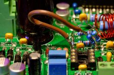
Here's a MacGyver version.

Tom
Could the extra wire be serving as either an antenna radiator or receiver, and then maybe the P2P cap nearby is receiving/transmitting and this is causing the HD to increase? The length of the loop is short so frequencies would have to be rather high. Dunno, but I do know that many times I have made an op amp circuit, especially higher gain ones, passing my hand nearby (12in away even), it certainly could be used as proximity sensor.
Hence, in part, the suggestions of post 357. Harmonics can indicate or contraindicate other mechanisms as well.That should be possible to tease out by looking at the FFT rather than the THD+N.
@tomchr
Can I resurrect this sleeping thread again? I have read all of your messages in this thread and also what you have written on your website and have one small question regarding:
"When designing a layout, it is important to return the load ground, the output compensation ground, and the low level (feedback and input) grounds to the circuit board common ground point through separate paths"
and the layout you posted in #181.
If I read this correctly, you do not have separate paths, but rather an unbroken ground on one side of the PCB. I assume that the size of this makes the resulting inductances small even if some components attach to this at separate points?
I would love to buy one of your PCBs, but I need to have a single supply sadly, so I guess I will have to create my own. The resulting unit will not be extreme HiFi either but rather rear speakers for 5.1, but I see no point in not striving for the very best 🙂
You have to pay attention to where the ground currents flow. Keep the ground impedances low.
You can keep the current separate in many ways. The simplest, but also the lowest performing, is to use separate traces. This method keeps the currents separate, but maximizes the ground impedance.
A better way is to use a ground plane for the large ground currents (power, speaker), pours where you really need a low impedance (feedback ground), and traces for reference/signal ground (or a pour if you can fit it).
The best method - but also the hardest to get right - is to use an unbroken ground plane for the power, speaker, and feedback grounds. The trick there is to keep the feedback ground in a quiet spot of the ground plane. Then use a large pour for the reference ground and join it with the rest at the speaker (-) output.
The layout shown in Post #181 has the feedback ground in the path from the speaker return to the supply caps, which is not optimal. That said, it isn't far from the supply caps...
Tradeoffs, tradeoffs.
Tom
True. It is all tradeoffs and I probably need not worry about that last bit of THD as I will use a radio link anyway for these 🙂
Sorry about waking a old thread...Here's the wire in question. I'll let the pros calculate the inductance of it to greater precision than my back-of-envelope estimate of 60 nH should they be so inclined.
Tom
About the measured differences with the wire loop:
Parasitic inductive coupling? From output section half-wave conduction and crossover current spikes travelling along power lines injected into this small loop. Small, but not for 0,000x% distortion....
If I not missed something...
A possibility to study.
Parasitic inductive coupling? From output section half-wave conduction and crossover current spikes travelling along power lines injected into this small loop. Small, but not for 0,000x% distortion....
If I not missed something...
Not inductive coupling, actually. Just the rise in impedance vs frequency caused by the added lead inductance.
Tom
In case you are wondering about the impact of lead inductance in the feedback network, attached are some measurements.
The bottom trace shows the THD+N vs Frequency of my Modulus-86 R2.0 amplifier.
The middle trace shows the impact of the lead inductance of a capacitor in series with the feedback resistor to ground. The capacitor was mounted to the PCB Macgyver style with rather long leads.
The top trace shows the impact of 60 mm (~2.25") of AWG20 wire in series with the feedback resistor to ground. 60 mm of wire has an inductance of approx. 60 nH.
The measurement was done at 35 W output power into 8 Ω using 60 kHz measurement bandwidth on my Audio Precision APx525.
It is very clear that in a precision circuit, the layout matters. Even 60 nH is enough to degrade the THD by 10 dB at 20 kHz.
Tom
Hi Tom, if i'm not mistaken, your lm3886 layout also have feedback resistor to ground trace very long, but you stated that at HF, its impedance is very small compare to 1K resistor so it's fine?
I don't understand your question. My LM3886DR has a low-inductance path to ground for the feedback network. You can see the performance measurements on its product page: LM3886 Done Right: Best DIY implementation of the LM3886 80W gainclone – Neurochrome
Is that what you're asking about?
Tom
Is that what you're asking about?
Tom
- Home
- Amplifiers
- Chip Amps
- LM3886 PCB vs Point-to-Point (with data)