But this one will be totally in class B. Which would give some crossover distortion.
See here some good bias circuit/alternative for the same concept.
http://electronicdesign.com/article/586/thd-enhanced-bias-circuit-design-targets-class-ab-.aspx
With kind regards,
Bas
The output xsistors are pure class B
but the chipamp delivers class AB to
the load until ~ 0.6 V through the
series resistor.
Granted hyper ' gm doubling ( or somesuch ) '
but the opampness compensates .....
The amazing thing is you almost don't need
heatsinks for the outputs 🙂
The output xsistors are pure class B
but the chipamp delivers class AB to
the load until ~ 0.6 V through the
series resistor.
Granted hyper ' gm doubling ( or somesuch ) '
but the opampness compensates .....
The amazing thing is you almost don't need
heatsinks for the outputs 🙂
Thanks hitsware,
you are talking about the second type of design, right ?
so, according to you it would work ?
what modifications would you recommend ? (adding caps to reduce noise ? changing res value...?)
My voltage regulator work on a similar principle but with BJT, so i m not sure about the mosfet (but i m here to learn)
Not gonna work if Q2 and Q4 drain is not connected to negative supply....
0.6 V through a 0.1 ohm resistor is 6 amperes, or 288 watts into 8 ohms/144 into 4 ohms, both impossible to reach with the supply voltage in question. That is probably why the heatsinks are not required, the transistors never actually turn on.
There is another thread on this kind of an amp, where a MOSFET follower is coupled to an opamp... http://www.diyaudio.com/forums/solid-state/172385-simple-ne5532-irf630.html
I can assume that for a power opamp, the current boost has to be worthwhile as the LM3886 can already deliver current in excess of its rated SOA, so the limitations are more from a thermal perspective. If you needed 20 or 30 amps from 3886, this might be the way to go but you'll have to be driving silly loads as the supply voltage is too low to get more than 80-90W out of it.
You can also look at common-drain operation with a slightly higher voltage for the output stage and a local feedback loop around the output. For a quick primer on MOSFETs and how they operate, look at the F5 manual, a very clear and insightful look at MOSFET basics.
Last edited:
Not gonna work if Q2 and Q4 drain is not connected to negative supply....
0.6 V through a 0.1 ohm resistor is 6 amperes, or 288 watts into 8 ohms/144 into 4 ohms, both impossible to reach with the supply voltage in question. That is probably why the heatsinks are not required, the transistors never actually turn on.
There is another thread on this kind of an amp, where a MOSFET follower is coupled to an opamp... http://www.diyaudio.com/forums/solid-state/172385-simple-ne5532-irf630.html
I can assume that for a power opamp, the current boost has to be worthwhile as the LM3886 can already deliver current in excess of its rated SOA, so the limitations are more from a thermal perspective. If you needed 20 or 30 amps from 3886, this might be the way to go but you'll have to be driving silly loads as the supply voltage is too low to get more than 80-90W out of it.
You can also look at common-drain operation with a slightly higher voltage for the output stage and a local feedback loop around the output. For a quick primer on MOSFETs and how they operate, look at the F5 manual, a very clear and insightful look at MOSFET basics.
Thank you very much sangram for this very seful reply.
My goal is to drive a lot of different paralleled identical speakers, thus felling to 2ohm. Wouldn t that kind of circuit be usefull then ?
I also have 0.4Ohm / 5W resistor;
would that be better ?
I corrected the mosfet connection (thanks for pointing that out, i was tired that night).
I ll have a look at your suggested reading materials, thanks again.
Attachments
Last edited:
I'm really a noob, but if I had to drive a 2 ohm load with lots of parallel speakers, I would personally look at a Class D solution. It works very well into difficult loads, and would cost much less to run in terms of energy bills.
I am assuming sound quality is not a priority or you would not be using this kind of a circuit in the first place, as distortion is much worse than the 3886 on its own. Also, 2 ohms in a bridge configuration is exclusively the domain of Class D, IMHO. I don't know if your circuit would survive longer than a second at full power.
The TDA 89xx series of chips from NXP can do what you want, over 100 watts into 2 ohm loads (though single-ended). And cheap, too.
Connexelectronic
http://www.classiccmp.org/rtellason/chipdata/tda8924.pdf
The 8950 delivers even more power, but minimum load is 4 ohms.
I'm really a noob, but if I had to drive a 2 ohm load with lots of parallel speakers, I would personally look at a Class D solution. It works very well into difficult loads, and would cost much less to run in terms of energy bills.
I am assuming sound quality is not a priority or you would not be using this kind of a circuit in the first place, as distortion is much worse than the 3886 on its own. Also, 2 ohms in a bridge configuration is exclusively the domain of Class D, IMHO. I don't know if your circuit would survive longer than a second at full power.
The TDA 89xx series of chips from NXP can do what you want, over 100 watts into 2 ohm loads (though single-ended). And cheap, too.
Connexelectronic
http://www.classiccmp.org/rtellason/chipdata/tda8924.pdf
The 8950 delivers even more power, but minimum load is 4 ohms.
Off course it is out of question that I put full power if connecting to a 2 ohm load (the regulator will shut down, there is a protection in it).
Thanks a lot for the TDA 89xx tip 🙂
I still want to solve the problem for my circuit (I also do it to learn).
would it work and how ....?
There is no protection for the output pair, so if you're using overcurrent protection on the power supply it should be safe.
AFAIK you have to be able to maintain a constant voltage at the gate of the MOSFET with respect to source to keep the device turned on (around 3V), and then as the voltage increases the device conducts more current.
That entire voltage is present across the 0.1 ohm resistor (or whatever you choose to use there). That is the problem with the circuit. A resistor high enough to create the threshold voltage will restrict the output of the LM3886 too much for it to be effective.
You can use bipolars in this circuit (I think) with a slightly higher value for R6 and it might work out. I'm not sure, but you also might need a Vbe multiplier like what Bas posted earlier, to protect the output pair. MJ2955/3055 SOA will not be much more than the LM3886 anyway, so it remains doubtful how useful the circuit will be.
This is where my competence ends. I do have an ideas for an opamp+MOSFET marriage but those are based on relatively low-current, low-voltage opamps. I'll write about it if I manage to get it working (not started yet). The basis for the idea is already there in the thread which I linked to earlier - flip the FETs around, put in a bit of local feedback to keep the gain in the output stage manageable, and run the output off a higher voltage.
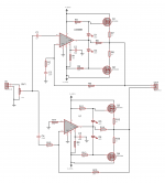
http://www.diyaudio.com/forums/atta...3641096-lm3886-irf540-irf940-mosfet-boost.gif
I mean like the above
Bipolar xsistors
No on bias
The op amp drives the load
through the resistor at low levels
when the signal comes up the
xsistors start to come on .... i.e.
when the voltage accross the
resistor > ~0.6V
The op amp would be your 3886
and the resistor ~ 10 Ohm
(for a start)
I mean like the above
Bipolar xsistors
No on bias
The op amp drives the load
through the resistor at low levels
when the signal comes up the
xsistors start to come on .... i.e.
when the voltage accross the
resistor > ~0.6V
The op amp would be your 3886
and the resistor ~ 10 Ohm
(for a start)
That's a really poor way to design a high power output stage unless you're building specialty lab equipment where high frequency noise must be kept to an absolute minimum. A speaker is not going to care about a little ripple at 500kHz or so.
That's a really poor way to design a high power output stage unless you're building specialty lab equipment where high frequency noise must be kept to an absolute minimum. A speaker is not going to care about a little ripple at 500kHz or so.
Please star882, be a little bit more precise than just "it s a poor way".
I don't have engineers knowledge so to me saying "it s a poor way" is useless,
I can't just guess why it would be poor. (unless your goal here is just to troll).
I'm here to learn, if people don't explain their comments, there is 0 added value to me.
Where is the 500kHz ripple comming from ?
To me there are 3 solutions:
-It works
-It works but there are some problems (What are they ?) or it isn't very efficient (then why?)
-It doesn't work (why?)
Or it looks bad to you just because usually people don't use mosfet that way?
(The design you sent in an earlier post is a class D which is totally different to what I m doing here)
Last edited:
It needs a charge pump to get enough drive voltage near the rails. Then it would be a good design for low power use.
It is very undesirable to operate power MOSFETs in a half-on "Tiffany Yep" mode, since they'll waste your power instead of using it to do useful work. (Unless you consider heating up your room useful work, maybe.) It is unavoidable due to laws of physics, but good high power designs try to keep that to a minimum. For audio, that means using a Delta Sigma modulator and high current MOSFET drivers.
It is very undesirable to operate power MOSFETs in a half-on "Tiffany Yep" mode, since they'll waste your power instead of using it to do useful work. (Unless you consider heating up your room useful work, maybe.) It is unavoidable due to laws of physics, but good high power designs try to keep that to a minimum. For audio, that means using a Delta Sigma modulator and high current MOSFET drivers.
thanks for the advice,
just a question , why "tiffany yep" ?
You are suggesting to use mosfet only with a Amp Class D, am I right ?
Since I have supply rails at +/-35V and I'll feed the load with a variable voltage,
I ll have heat generated whatedver I do, or there is a way ? (am i wrong?)
just a question , why "tiffany yep" ?
You are suggesting to use mosfet only with a Amp Class D, am I right ?
Since I have supply rails at +/-35V and I'll feed the load with a variable voltage,
I ll have heat generated whatedver I do, or there is a way ? (am i wrong?)
The "Tiffany Yep" mode is named after an engineer/model. (For a little background info, go to 2008-09 Miss Chinatown Houston and scroll to the bottom.) When a transistor is in the "Tiffany Yep" mode, it dissipates a significant amount of energy, causing it to get hot. Hence the joke that the transistor is trying to imitate Tiffany Yep instead of working efficiently. (The irony is that Tiffany Yep is a digital communications engineer, but a friend of mine came up with the term and it stuck.)
That applies to any transistor, not just MOSFETs. It definitely applies to IGBTs. But for ordinary bipolar transistors, it's a little complicated since overdriving bipolar transistors causes them to slow down. But bipolar transistors are not used very much in modern high power circuits.
FWIW, a power electronics professor (Dr. Ehsani) at Texas A&M thinks of operating a power transistor in "Tiffany Yep" mode as like going full throttle in a car while riding the brakes to control speed. It's just not a good way to do it!
The class D approach (which includes both "pure" digital and hybrid digital) is essentially a buck converter or two with a varying output voltage. Excess voltage is essentially converted into current, just as in a switching power supply.
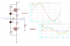
After investigating more,
in order not to waste the capabilities of the LM3886,
a circuit like hitsware suggest would work great,
with MOSFET it should work too,
look at the simulation I ran.
The yellow curve is the current from the LM3886.
I'm pretty sure bipolars will work better for this circuit
They turn on smoother than mosfets and need no bias
(in this case)
That applies to any transistor, not just MOSFETs. It definitely applies to IGBTs. But for ordinary bipolar transistors, it's a little complicated since overdriving bipolar transistors causes them to slow down. But bipolar transistors are not used very much in modern high power circuits.
thanks a lot for all the explanations.
The difference for BJT makes them more suitable or not ?
(If I limit the base current)
Hitsware, thanks for you opinion. I would actually love to run test but I don t have the needed tools to compare them.
---
The Class D is my next poject (I have a function generator waiting for that, it will be full analog type) 😉
Last edited:
- Status
- Not open for further replies.
- Home
- Amplifiers
- Chip Amps
- Lm3886 + irf540/irf940 (mosfet) ?