Hello all,
I have a few LM3886 and a very strong power supply.
I would like a few more Amp to be able to flow trough the output...
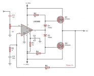
So I thought "what if I add some mosfet there?"
would that scheme work ?
Would another (similar) design work ?
what if I use a bipolar based design instead of mosfet ?
and would this thing would be able to deliver the 15A my regulator is able to supply ?
Sorry if those are very stupid questions...
I have a few LM3886 and a very strong power supply.
I would like a few more Amp to be able to flow trough the output...
So I thought "what if I add some mosfet there?"
would that scheme work ?
Would another (similar) design work ?
what if I use a bipolar based design instead of mosfet ?
and would this thing would be able to deliver the 15A my regulator is able to supply ?
Sorry if those are very stupid questions...
Attachments
Something similar should work. I didn't look at your circuit in detail but there are many similar "current booster" ideas that have been used successfully, especially with opamps in place of the chipamp.
There are some application notes with similar ideas and topologies, such as AN-272 at national.com and AN18 at linear.com. But none of the ones I saw used MOSFETS.
Maybe someone could try simulating something very similar in LTspice.
There are some application notes with similar ideas and topologies, such as AN-272 at national.com and AN18 at linear.com. But none of the ones I saw used MOSFETS.
Maybe someone could try simulating something very similar in LTspice.
I've used this approach and it works well :
But this one will be totally in class B. Which would give some crossover distortion.
See here some good bias circuit/alternative for the same concept.
http://electronicdesign.com/article/586/thd-enhanced-bias-circuit-design-targets-class-ab-.aspx
With kind regards,
Bas
or just use one of the lme498xx ic's from national designed to drive fets and bjts.
lme49830
Thanks a lot for all your advices,
you are very right that an opamp would work as well.
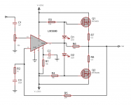
I tried to modify the design according to what you said and I have no clue if it would work or not.
I have also no clue about the right values for the resistors R6 to R8, nor how to calculate it.
you are very right that an opamp would work as well.
I tried to modify the design according to what you said and I have no clue if it would work or not.
I have also no clue about the right values for the resistors R6 to R8, nor how to calculate it.
Attachments

Thanks a lot to everyone for all your advices.
It is right that I might as well use an op amp,
it s just that I don t have one going up to +/-35V.
I feel bad wasting the capabilities of the LM3886.
I tried to change the design based on your comments.
I have no clue what value I should use for the resistors R6 to R8, neither how to calculate it, nor if it s useful for my case...
Attachments
Thanks a lot to everyone for all your advices.
It is right that I might as well use an op amp,
it s just that I don t have one going up to +/-35V.
I feel bad wasting the capabilities of the LM3886.
I tried to change the design based on your comments.
I have no clue what value I should use for the resistors R6 to R8, neither how to calculate it, nor if it s useful for my case...
In my opinion, R6 can be omitted. R6 would only be needed if it was a class B amplifier, in that case it would conduct voltage direct from the op-amp below 0,7 volt when the transistors are switched off. R7 and R8 should be as low as possible, but high enough to maintain thermal stability. I am not good with MOSFET's but with BJT's the value is often 0.22Ohm.
Please refer also this example, for a better bias setup then putting your signal all direct through the diodes/LED's in the bias string: http://electronicdesign.com/article/586/thd-enhanced-bias-circuit-design-targets-class-ab-.aspx
With kind regards,b
Bas
Bedankt, Bas
wouldnt the amplifier correct the bias by itself ?
Bedankt, Bas
wouldnt the amplifier correct the bias by itself ?
Ha Dutch too?

To be honest, I am not knowledgable about MOSFET's and if they need to be compensated or not. In case of BJT's you need thermal compensation, either with a VBE transistor mounted on the heat-sink, or diodes in the bias string mounted on the heat-sink. I am sure other members can provide better input about your case.
I do like the LED's in your bias string, but they don't contribute to thermal compensation.
With kind regards,b
Bas
Ha Dutch too?
Bas
No, french-swiss lost in canada...
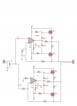
Be carefull on my schematic the 2nd mosfet is upside-down.
I corrected this and also added a second block to get a bridged configuration.
Attachments
The circuit will probably work OK, but will also have some crossover distortion. Also the voltage swing will be reduced because of the Vgs of the MOSFETs. If the original circuit can get full output swing into the load, then the revised circuit is actually worse in that regard.
I'm surprised no one told you that Q2 is up side down.
I'm surprised no one told you that Q2 is up side down.
Would a LME49830/11/10 be too complicated for you to implement? If you want to give any of those a try, send me a PM.
I can investigate that way. Thanks for the suggestion.
star882 said:None of the circuits posted will properly drive the MOSFETs. A charge pump is needed to derive the gate drive voltage for the high side NMOS. And using a PMOS for the low side is just silly.
I m not an engineer and never stuied electronics in any other way than by myself. So I have trouble understanding this reply.
I just reproduced the `silly` thing found there: MOSFET Push Pull Power Amplifier - Electronics Tutorials
You seem to be quite comfortable with mosfet... do you know any schematic showing the `right way` ? (I need help here)
Or a reference page that you like (I read a lot about mosfet before trying to use it, and it is while reading about this that I found the schematic.
If I read wrong materials it will lead me nowhere, that is why i m counting on you)
if I just replace the mosfet with BJT, would that work ? (TIP3055, TIP2955 which I have in stock)
sawreyrw said:Thanks for your input,
So I would rather use the first circuit with an opamp capable of working with a +/-35V swing.
http://www.nxp.com/documents/user_manual/UM10155.pdf
That's a completely discrete circuit, but note how the gate drives are designed to source and sink a lot of current for fast switching. That avoids the half-on "Tiffany Yep" mode of operation.
That's a completely discrete circuit, but note how the gate drives are designed to source and sink a lot of current for fast switching. That avoids the half-on "Tiffany Yep" mode of operation.
- Status
- This old topic is closed. If you want to reopen this topic, contact a moderator using the "Report Post" button.
- Home
- Amplifiers
- Chip Amps
- Lm3886 + irf540/irf940 (mosfet) ?