Hi,
I said "fullrange" cause my previous builds was for biamping. Here it's was to drive mainly fullrange drivers 4 to 8 ohm..
First, I have to thank AndrewT, Mark Whitney, Tomchr and Danielwritesbac. I'm Sorry if I forgot someone..
I'm collected their advices, and I decided to build a new amp with LM3886 in dual mono setup.
I don't need high power (maybe 25 watts) cause speaker I have is 90 to 97 db, and for a quiet listening. But I hope have a good sounding.
The end result might look like this :
Except one pot for this new..
PCB' come from chipamp : Chipamp Electronics
the heatsink :
Schematic diagram :
Two safety loop breaker, one per side :
dual mono psu with snubber :
amp schematic :
components :
close up Caddock MK132 330 Ohm :
I hope nothing is wrong or missing !
I work slowly (turtle ?), so it's was finish maybe next year..
Phil.
PS : adding full schematic with labels :
Some picts are missing in this tread, you can see them here :
http://www.diyaudio.com/forums/chip-amps/265827-lm3886-fullrange-9.html#post4261632
I said "fullrange" cause my previous builds was for biamping. Here it's was to drive mainly fullrange drivers 4 to 8 ohm..
First, I have to thank AndrewT, Mark Whitney, Tomchr and Danielwritesbac. I'm Sorry if I forgot someone..
I'm collected their advices, and I decided to build a new amp with LM3886 in dual mono setup.
I don't need high power (maybe 25 watts) cause speaker I have is 90 to 97 db, and for a quiet listening. But I hope have a good sounding.
The end result might look like this :
An externally hosted image should be here but it was not working when we last tested it.
Except one pot for this new..
PCB' come from chipamp : Chipamp Electronics
An externally hosted image should be here but it was not working when we last tested it.
the heatsink :
An externally hosted image should be here but it was not working when we last tested it.
Schematic diagram :
An externally hosted image should be here but it was not working when we last tested it.
Two safety loop breaker, one per side :
An externally hosted image should be here but it was not working when we last tested it.
dual mono psu with snubber :
An externally hosted image should be here but it was not working when we last tested it.
amp schematic :
An externally hosted image should be here but it was not working when we last tested it.
components :
An externally hosted image should be here but it was not working when we last tested it.
close up Caddock MK132 330 Ohm :
An externally hosted image should be here but it was not working when we last tested it.
I hope nothing is wrong or missing !
I work slowly (turtle ?), so it's was finish maybe next year..
Phil.
PS : adding full schematic with labels :
An externally hosted image should be here but it was not working when we last tested it.
Some picts are missing in this tread, you can see them here :
http://www.diyaudio.com/forums/chip-amps/265827-lm3886-fullrange-9.html#post4261632
An externally hosted image should be here but it was not working when we last tested it.
Last edited:
Don't connect Cf to -IN.
Connect Cf between +IN and Signal Return.
R2 should roughly match Rf
Connect Ci to R2 and to Cf and to Signal Return at the input socket.
Connect C1 to C2
Connect Cz to the junction of C1/2.
This becomes your Power Ground.
The route from Pin3 through RzCz through C1 to Pin1&5 MUST be VERY short.
The route from Pin3 through RzCz through C2 to Pin4 MUST be VERY short.
All of these components (except the two electrolytics) MUST be kept VERY close to the chip amp package at the Pin1,3,4,5 end.
Connect the incoming PE wire DIRECT to Chassis at the incoming hole/socket (if IEC or similar).
ESP shows a long connection through other components. ESP's method is not good practice.
BTW,
you can add a switch across The Disconnecting Network (Safety Loop Breaker), i.e. parallel to the R & C.
This optional switch becomes your ground lift switch (the safe way !!!!!).
Last edited:
Thank's, it's mistake, I will change schematicDon't connect Cf to -IN.
Connect Cf between +IN and Signal Return.
Yo think it's better when R2 is equal (or nearly) Rf, I read somewhere that it was necessary that R2 was always less than RfR2 should roughly match Rf
It's my fault, C4 is missing, I should write (C3 C4) and not (C2 C3), sorry.Connect Ci to R2 and to Cf and to Signal Return at the input socket.
Connect C1 to C2
Connect Cz to the junction of C1/2.
This becomes your Power Ground.
I will see with pcb, but it's small, not sure I can change many things.The route from Pin3 through RzCz through C1 to Pin1&5 MUST be VERY short.
The route from Pin3 through RzCz through C2 to Pin4 MUST be VERY short.
All of these components (except the two electrolytics) MUST be kept VERY close to the chip amp package at the Pin1,3,4,5 end.
Yes, is provided.Connect the incoming PE wire DIRECT to Chassis at the incoming hole/socket (if IEC or similar).
Sorry, what do mean by ESP ?ESP shows a long connection through other components. ESP's method is not good practice.
Good idea.BTW,
you can add a switch across The Disconnecting Network (Safety Loop Breaker), i.e. parallel to the R & C.
This optional switch becomes your ground lift switch (the safe way !!!!!).
Phil.
if the BJT input pair have exactly the same Ic, same Vce, same Tj and exactly the same hFE, then they will have the same Ib. Ib passes through those two resistors.................... Rf, I read somewhere that it was necessary that R2 was always less than Rf
If the voltage drop across those two resistor is different, then the difference is the output offset.
If the two input resistors are not well matched either due to Ic being different, or due to different device parameters, then Ib is usually different. That is the specification value: input offset current.
Your first try assumes Ib will be the same and then adjust one of the resistors to equalise the V at the two input pins, since with a chipamp you cannot adjust the Ic.
the 5th diagram is a crib from esp with the copyright logo removed and the language changed.what do mean by ESP ?
Hi Phil. I've used those boards with the specified component values and a single PSU, it's an easy build and it works exceptionally well.
Just be careful not to do what I did! I used screws with too big a head on them to fasten the boards with, it shorted out a track which fried some PSU diodes. I refitted the boards using insulating fibre washers on each side.
Good luck with your build.
Davy
Good luck
Just be careful not to do what I did! I used screws with too big a head on them to fasten the boards with, it shorted out a track which fried some PSU diodes. I refitted the boards using insulating fibre washers on each side.
Good luck with your build.
Davy
Good luck
Last edited:
Hi Davy,
I build one (first pict first post), and yes I found some small holes..
I use this plastic brace :
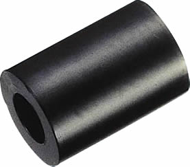
with screws..
On amp pcb, some hole was to small for output for example..
I will use terminals for psu and amp supply.
Thank's.
Phil.
I build one (first pict first post), and yes I found some small holes..
I use this plastic brace :
with screws..
On amp pcb, some hole was to small for output for example..
I will use terminals for psu and amp supply.
Thank's.
Phil.
Thanks for the recognition. Glad I could help.
I recommend adding a Thiele network on the output. You can do that between the board and the output connector. The Thiele network is the inductor in parallel with a resistor. It is needed for stability with capacitive loads (think long speaker cables or electrostatic speakers). You can wind the inductor yourself...
These guys have a good air core inductance calculator. You'll want something in the 700 nH to 1 uH range.
The commonly used Thiele network is 10 Ω, 2 W in parallel with 0.7-1 µH.
I would build the boards as-is and just add the Thiele network. There's no point in turning this into a point-to-point wiring exercise if you already have the boards. That said, the board layout can be improved considerably. Specifically, the inductance of the ground net is way larger than it needs to be. This reduces the effectiveness of the decoupling network and the Zobel network (R+C from output to ground). The LM3886 needs a decoupling network consisting of a bulk electrolytic cap, a smaller electrolytic or tantalum, and a ceramic or film cap. This is spelled out in the LM3886 data sheet, actually. My recommendation is to use 1000 µF electrolytic + 22 µF low ESR, ESL electrolytic (or OSCON) + 1 µF X7R ceramic. I don't see a way to get those components on the board, cleanly.
It looks like the board was optimized for size rather than performance. Nothing wrong with that, I just personally prefer to optimize for performance. I guess I should look at the positive side of this... When you're ready to upgrade to a Modulus-86, I'll be happy to sell you a couple of boards... 🙂
If you haven't already, I suggest that you take a look at my Taming the LM3886 website. I cover stability, thermal design, decoupling, power supply design, and more.
~Tom
Last edited:
Hi Tom,
Thank's for interest..
At first time, I thought "it's not necessary", and what good resistor I can use for that ? Caddock ?
But I will try this network to hear some difference with sonics..
I read about your Modulus 86, great job, maybe next year I try it !
Phil.
Thank's for interest..
Yes I read some advices about Thiele network, I left aside, cause speakers are 92 to 97 db, I don't need much power (maybe 10 watt max for a party). Length cables are 2,5 meter with two Cat 5 wire per side.Thanks for the recognition. Glad I could help.
I recommend adding a Thiele network on the output. You can do that between the board and the output connector. The Thiele network is the inductor in parallel with a resistor. It is needed for stability with capacitive loads (think long speaker cables or electrostatic speakers). You can wind the inductor yourself...
At first time, I thought "it's not necessary", and what good resistor I can use for that ? Caddock ?
But I will try this network to hear some difference with sonics..
Yes, but like you said I don't see a way to get those components on the board..The LM3886 needs a decoupling network consisting of a bulk electrolytic cap, a smaller electrolytic or tantalum, and a ceramic or film cap. This is spelled out in the LM3886 data sheet, actually. My recommendation is to use 1000 µF electrolytic + 22 µF low ESR, ESL electrolytic (or OSCON) + 1 µF X7R ceramic. I don't see a way to get those components on the board, cleanly.
If you haven't already, I suggest that you take a look at my Taming the LM3886 website. I cover stability, thermal design, decoupling, power supply design, and more.
~Tom
I read about your Modulus 86, great job, maybe next year I try it !
Phil.
I used that kit to drive 89dB 6ohm speakers through 7 metre cables with no Thiele network, it sounded very good indeed so I didn't see the need to add one.
It is beaten by the more complex and better designed My-Ref FE mono blocks I built (but not by a huge margin).
It is beaten by the more complex and better designed My-Ref FE mono blocks I built (but not by a huge margin).
The 1000u fit on top of the board, the 100n ceramic bypass caps can fit on the bottom of the board.Yes, but like you said I don't see a way to get those components on the board.
220u CI fits with a mild shove and doesn't fit completely flush with the board, but that's okay. Bypass cap for CI may be added later if more airy treble is desired and a rather basic guesstimated value for bypass at that locale is 10n polyester (a mylar dip cap is suitable), and it fits directly onto the 220u's pins, accessible on the bottom of the board.
Your schematic is looking highly usable.
For ease, I would suggest to get one channel up and running before building the other channel.
Last edited:
Hi Daniel,
Thank's, I will try like you said..
Here's how I work (my previous build) :
More easy to change components, and enough for listening.
Phil.
Thank's, I will try like you said..
Here's how I work (my previous build) :
An externally hosted image should be here but it was not working when we last tested it.
More easy to change components, and enough for listening.
Phil.
It is a nicely clean work; however, you do need to spiral twist all of the cables.
Also consider that heatsinks work when there is cool air intake underneath the heatsinks with the fins positioned vertically (so that air will move through the heatsink).
Cool air intake is accomplished by either having the heatsinks outside of the case (typically on the back panel), or by using cool air intake vents under the heatsink (through the bottom of enclosure that has feet so that air can get under it) along with hot air output at/near the top of the enclosure (to let the hot air out).
Hi Daniel,
Thank's.
About heatsink, it's just for try, it is never very hot at listening, maybe 30/35 °.
I began to build the psu's, but at his time I wonder if I canot build monoblock amp's ?
The only advantage would be a separate audio ground, but not only ?
Phil.
Thank's.
About heatsink, it's just for try, it is never very hot at listening, maybe 30/35 °.
I began to build the psu's, but at his time I wonder if I canot build monoblock amp's ?
The only advantage would be a separate audio ground, but not only ?
Phil.
Dual mono (shown in your first picture at post1) is electronically similar to monoblocs and should not vary in any way except for the number of amplifier enclosures.
Hi,
So if it's the same, let's go to dual mono in one box..
And better for my bank account !!
Phil.
So if it's the same, let's go to dual mono in one box..
And better for my bank account !!
Phil.
Hi,
For heatsink, I have two choices, this one (from an old amp) :
Or this for separate heatsinks :
I have not the specs, but I think it's big enough in my case (28 volts and about 4 Ohm load)..
There is a way to estimate power dissipation with size and weight ?
Phil.
For heatsink, I have two choices, this one (from an old amp) :
An externally hosted image should be here but it was not working when we last tested it.
Or this for separate heatsinks :
An externally hosted image should be here but it was not working when we last tested it.
I have not the specs, but I think it's big enough in my case (28 volts and about 4 Ohm load)..
There is a way to estimate power dissipation with size and weight ?
Phil.
Yes, some free software makes a very good prediction of the C/W for Rth s-a.
I'd guess that is between 1C/W and 2C/W
Compare those to the table in the datasheet and see if your proposal in the the "ballpark".
I'd guess that is between 1C/W and 2C/W
Compare those to the table in the datasheet and see if your proposal in the the "ballpark".
Hi,
I gathered all the elements on a single file, with labels :
High def > right click > show picture
Phil.
I gathered all the elements on a single file, with labels :
An externally hosted image should be here but it was not working when we last tested it.
High def > right click > show picture
Phil.
Last edited:
- Status
- Not open for further replies.
- Home
- Amplifiers
- Chip Amps
- LM3886 "fullrange"