Just make sure your "PWR_GND" and "SIG_GND" are connected "somewhere" otherwise you end up with the output at V- or V+. (don't ask me how I know)

I'm happy with it. My schematic is slightly different but nothing that would make a difference. I omitted the mute as I put a mute relay, some different capacitors from what I had in stock. It is stable so that is the most important. A bit larger PSU caps but that is more because I have 4 amps on the same psu for these active speakers.
Tasarımı küçük tutmak için bunu yaptım ve herhangi bir kapasitör eklemedim devraldım çünkü her kanala 80.000uf kapasitör ekleyeceğim.
 English please.
I did this to keep the design small and didn't add any capacitors, I took it over because I'm going to add 80,000uf capacitors to each channel.
English please.I did this to keep the design small and didn't add any capacitors, I took it over because I'm going to add 80,000uf capacitors to each channel.
Attachments
Last edited by a moderator:
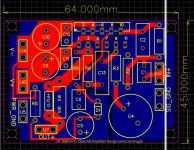
Are you using M3 screws to hold your pcb in the chassis? Then make sure you have at least 7mm diameter (solder and component side) around the hole free to put a washer.
Actually, this is a demo card, I printed 5 copies to try it out but I haven't received it yet. I will mount the PCB vertically rather than horizontally.
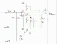
C6 should be 100nf, not 4.7uf! No need to use D1, just use 27k for R5. Otherwise everything is fine. For power supply use 10000uf 50v capacitors per rail. Good luck.
Do you think there is a need to add an op amp to the input? What effect would it have if I added it?
I don't think there is any need of it because the amplifier is in non-inverting configuration.
I refer you to this website for everything regarding LM3886 chip amplifier...
https://neurochrome.com/pages/supply-decoupling
https://neurochrome.com/pages/supply-decoupling
"100uf Nichicon Gold" ?
what are those?
Anyway, for c9/c10 you could use literally any electrolytic caps 22uf-100uf 50V or more. My favorites for that position are Panasonic FM/FR/FS/FC series.
what are those?
Anyway, for c9/c10 you could use literally any electrolytic caps 22uf-100uf 50V or more. My favorites for that position are Panasonic FM/FR/FS/FC series.
No need of an opamp if you are using it like a power amp - volume controlled by sourceDo you think there is a need to add an op amp to the input? What effect would it have if I added it?
BUT If you are planning to add a volume control pot or need higher gain with low noise, then you may require an opamp at input
See this video
Research by Tom Christiansen shows that a 4.7 µF ceramic X7R capacitor in parallel with a 22 µF electrolytic and 1000 µF electrolytic has significantly better performance than the paralleled 100 nF, 10 µF, and 470 µF capacitors recommended in the datasheet.Is it necessary to use low esr capacitor for c9 c10? Or can we use 100uf Nichicon Gold there?
https://www.circuitbasics.com/design-hi-fi-audio-amplifier-lm3886/
C6 capacitor is maybe too high value, it will heat up 4R7 resistor...
High frequencies will be affected, if this amp will drive sub then it is ok, but if it is for full range speaker, I wouldn't put capacitor of this high value.
High frequencies will be affected, if this amp will drive sub then it is ok, but if it is for full range speaker, I wouldn't put capacitor of this high value.
I will pay attention to all your answers. Guys, I wrote the C6 capacitor wrong, it will be 100nf.
That circuit should work just fine. It's basically a copy of the circuit in the data sheet with some modifications to the MUTE circuitry.
I don't personally see the point of using a zener diode in the mute circuit, but some do set it up that way. I'd move the connection to C5 from the zener anode to the zener cathode. You do want the voltage on the MUTE pin to be somewhat clean.
Tom
I don't personally see the point of using a zener diode in the mute circuit, but some do set it up that way. I'd move the connection to C5 from the zener anode to the zener cathode. You do want the voltage on the MUTE pin to be somewhat clean.
Tom
Thanks Tom. It's nice to hear this and get a suggestion from a master like you. I am dealing with the supply of components. When I receive all of them, I will share the results here.
- Home
- Amplifiers
- Chip Amps
- LM3886 Circuit Design