Hey, so what is it you'd like to accomplish? Can you possibly redraw this as a schematic?
a) Drastically increase input impedance to say 50KΩ so that this can act as a general purpose amplifier for line level sources, 2KOhms output impedance or even more.
b) A nice to have would be if I could manipulate the gain of this stage, and most probably lower it.
Do try to have a look at the picture with same symbols at connection points, it will become clear quickly. What program would you recommend to a beginner if they want to make a proper circuit diagram out of this?
Last edited:
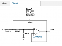
I personally think it's set it up like this photo. Those two resistors are likely biasing the input signal to at 1/2 Vcc instead of at 0.
The gain is likely set using the 50k one. I think it's pretty safe to mess with that one.. Problem is the input capacitor and whatever capacitor are close might be forming a filter network, so if you change one it could mess with the cutoff frequency of the amp.
I think it should be pretty safe to put a resistor in parallel with the large 55k one to test..
Attachments


a) Drastically increase input impedance to say 50KΩ so that this can act as a general purpose amplifier for line level sources, 2KOhms output impedance or even more.
b) A nice to have would be if I could manipulate the gain of this stage, and most probably lower it.
Do try to have a look at the picture with same symbols at connection points, it will become clear quickly. What program would you recommend to a beginner if they want to make a proper circuit diagram out of this?
Try out Kicad.. It's free and runs on all platforms.
Try out Kicad.. It's free and runs on all platforms.
Quick question. Lets say I fried both my chip op amps left and right and I removed them. What would happen if I connected my source left to where the left opamp's out was, and right to where the right opamp's out was. As you can imagine, I'm trying to see if there's a way to cleanly bypass this stage altogether.
Sorry, what is it you're trying to do again? Why not just build a new LM3886 board if you want to get rid of the opamp gain stages. I'm happy to help you figure this out, but might be easier just to get what you need instead of modifying this.
Sorry, what is it you're trying to do again? Why not just build a new LM3886 board if you want to get rid of the opamp gain stages. I'm happy to help you figure this out, but might be easier just to get what you need instead of modifying this.
Somehow cleanly bypass the preamplification stage altogether, hoping what comes next has greater input impedance.
If you don't really care what happens to it (ie if you're considering ripping out the preamp altogether), here's what I would try.
1) Try changing that 55k resistor to something else. As a quick and dirty test, you can touch another resistor to it in a parallel. I'd try a 10k resistor to start.
2) You can rip out that 2.2k near the opamp and replace it to something like a 10k. Just bear in mind it's probably working with the 55k to set the gain. So setting it to 55k and leaving the other one might result in unity (i.e. 1.0) gain roughly and a 55k input inpedence. It may cause a loss of frequency result though, but you should be able to hear that. The first is pretty easy to do.
2a) if you don't hear a frequency loss, you're golden
2b) if you do, try 10k for the input resistor, and temporarily solder a 12.5k resistor onto the 55k one. That'll bring the total resistance down to about 10k, which should be about unity gain.
Bear in mind that as always, horrible things can happen 🙂 But if it was my amp I'd be playing with that.
If you don't really care what happens to it (ie if you're considering ripping out the preamp altogether), here's what I would try.
1) Try changing that 55k resistor to something else. As a quick and dirty test, you can touch another resistor to it in a parallel. I'd try a 10k resistor to start.
2) You can rip out that 2.2k near the opamp and replace it to something like a 10k. Just bear in mind it's probably working with the 55k to set the gain. So setting it to 55k and leaving the other one might result in unity (i.e. 1.0) gain roughly and a 55k input inpedence. It may cause a loss of frequency result though, but you should be able to hear that. The first is pretty easy to do.
2a) if you don't hear a frequency loss, you're golden
2b) if you do, try 10k for the input resistor, and temporarily solder a 12.5k resistor onto the 55k one. That'll bring the total resistance down to about 10k, which should be about unity gain.
Bear in mind that as always, horrible things can happen 🙂 But if it was my amp I'd be playing with that.
Absolutely, such modules were given for fun and experimentation. So, this is the "Look ma, no op amps!" post:
This is what I meant with my obscure earlier post about bypassing the preamplification stage. The picture was taken with the amp properly powered up, no op-amps, and my input directly to where the op amp outputs are. Music playing normally.
Damn, this thing sounds glorious. It sounds so great after another smaller class-T module I had hooked up while I was fiddling with the circuit.
Unexpectedly enough, the gain is the exact same. If there is any difference, it is very slight. Most probably loudness is the exact same and it's a psychological effect.
Now the big mystery is, what happened to the input impedance? I 'll use my crude testing method to test it out ASAP.
Based on that photo you posted, that pin is the input, no? That might be why it sounds the same. I believe both opamps are in the same orientation. You might want to try going directly to the output pin instead.
Both cables are on the output pin, although it's not very clearly visible with the black cable. It's black-left, brown-ground, orange-right.Based on that photo you posted, that pin is the input, no? That might be why it sounds the same. I believe both opamps are in the same orientation. You might want to try going directly to the output pin instead.
I was horribly wrong about the gain. I used my 1KHz and 600Hz tones again, with my sound card volume fixed at 13/100. It was as loud as I could go at this time of the day. I measured AC rms at the speaker terminals.
Without the opamps, signal plugged into where the opamp output would be:
1KHz: 4.194VAC
600Hz: 4.096VAC
I then reinstalled the opamps to see the original rms values, I was greeted with a very much audible noise floor, in your (my) face. This is the part I got horribly wrong. Measurements were:
1KHz: 17.7VAC
600Hz: 17.3VAC
That was loud, and I don't know how good it was for my tweeter. I reckon AC rms value is proportional to signal amplitude, so dividing the opamp by no-opamp values it seems I got rid of about 4.22x of gain. I don't know if this was expected based on the values on the NE5534 resistor/cap network.
But what about impedance? you say. So, with the opamps still off, I did the same series resistance trick at the input to lower speaker AC voltage to half. My impedance values were:
1KHz: 9.41KΩ (initial: 2.6KΩ)
600Hz: 9.63KΩ (initial: 2.84KΩ)
So compared to my initial measurements with the opamps on, I got an increase in impedance of about 3.5 times. While not ideal, it is very welcome, as is losing over 4x gain from the opamps.
I wonder if there's anything left from the input stage I crudely bypassed, that's keeping impedance down. If tapping into a different part of the circuit or removing something would give me something close to 20KΩ, I'd be a happy camper.
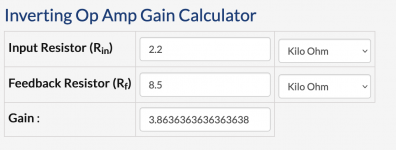
I'm pretty lost with regards to that op-amp then. When I looked at the colour codes, it looked like you had a 2.2k, 8.5k, and a 20k resistor.
If the 2.2 was input and the 8.5 output, that's a gain of around 4. But otherwise I don't know why you go those values..
If the 2.2 was input and the 8.5 output, that's a gain of around 4. But otherwise I don't know why you go those values..
Attachments
I'm pretty lost with regards to that op-amp then. When I looked at the colour codes, it looked like you had a 2.2k, 8.5k, and a 20k resistor.
If the 2.2 was input and the 8.5 output, that's a gain of around 4. But otherwise I don't know why you go those values..
Your color code identification and calculations match my measured gain of 4.22x then. Everything seems consistent, except my measurements on the board where I've probably made some erroneous assumption or other mistake.
You mention an opamp buffer. I didn't even know such things exist. 🙂 Well, I kind of did know there's something like that, but wouldn't know where to look or what to get. If I get such a thing I'd like it to be simple, inexpensive, and not degrade the sound. Not sure if sound degradation by this extra stage is a concern though. The seller of this board mentions its NE5534 preamp stage can be "used as a buffer", so I was kind of hoping that could work as a high impedance input/low impedance output. I'm still waiting for him on that.
In any case, do you perhaps have any recommendations for such a high input/low output impedance buffer?
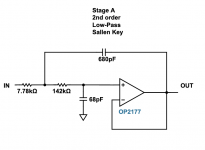
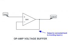
Usually you just use an opamp with a gain of 1. It basically isolates the input from a high load and can handle a higher load output. I personally have been using a OPA2134 opamp myself since it's recommended as one of the best low noise audio opamps. With two capacitors and two resistors and an appropriate power supply you could set it for a low pass filter (22kHz).
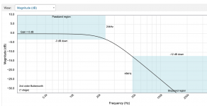
Something like this will have unity gain (won't amplify or attenuate), but will be able to higher more load at the output. I set it to have a passband from 0Hz to 22.05kHz. Basically because the opamp is active (i.e. powered), it doesn't care as much about input impedence of the next area since it has power to overcome it. Many times you'll see a opamp with a gain of 1, i..e a buffer, to separate a low impendence device from a high impedance one
Attachments
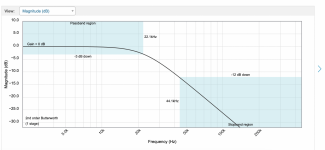
Which looks like this.. I.e. a flat passband for audio frequencies, and a gain of 1. But it can drive a higher load (i.e. lower input resistance).
There seems to be a slight loss of very high treble but it should be ignorable. This would be a very useful module if I could put one together. What would be its input and output impedances? Also, power requirements?
There seems to be a slight loss of very high treble but it should be ignorable. This would be a very useful module if I could put one together. What would be its input and output impedances? Also, power requirements?
You can modify the parameters yourself if you want. You can extend the passband out to 24kHz if you want, https://tools.analog.com/en/filterwizard/
Specs say about 40ma per opamp. The only trick is it needs a dual supply usually, so if your source is +/- 4V you probably need +/- 5V. You can attenuate it of course. You can also do it with a single supply, but it's tricker as you need to bump your signal up to a DC value, run it through the opamp, then us a DC blocking capacitor at the end to center it at 0 again.
The input impedence is high, often infinity on paper (as it's active, it can power its own output, which is why it's a buffer). It's much much larger than your preamp for sure.
You could experiment with using a voltage divider in front of it, i.e. a 30K and a 10K resistor, taking the input off the 10K, which is 25%.. that might balance out the 400% gain you are seeing.
Here is a filter with a passband of 24kHz (that's the 3db point, so it's dropping there.. but for most audio, it's negligible there at that point). I personally can't hear above 16khz these days.
Attachments
- Home
- Amplifiers
- Solid State
- LM3886 amplifier input impedance