Hello all,
I have this LM3886 based amplifier board. I want to use a small passive mixer as a source for it. The thing is, the passive mixer has something like a 2KOhm output impedance, which is kind of high. So, thinking that I need at least 20KOhm input impedance at the amplifier input, I set out to find out what it actually is.
Checking the manufacturer's spec sheet did not mention input impedance. Upon inquiry, they mentioned that the amplifier has a preamplifier stage, and that its input impedance is 2.2KOhms.
Upon seeing this quite low number, I thought it was possible they didn't have a clue what they were talking about. So I set out to try to estimate it myself. I used the following video:
The trick is adjusting an external trim pot until the output amplitude is halved, then you can disconnect and measure your input resistance at the trim pot. The only thing I did differently was instead of using an oscilloscope to check output amplitude, I used a normal multimeter to measure AC rms voltage since I reckoned it's proportional to amplitude thus an equivalent measurement.
I used two test signals, one at 1KHz and one at 600Hz, of the same amplitude. Interestingly enough, my measurements for impedance with this method were 2.6KOhm @1KHz and 2.84KOhm @600Hz. The trick seems to at least yield higher impedance for lower frequencies and for certain the numbers are of the same order of magnitude as what the manufacturer claimed.
Now, supposing we have a source of about 2KHz output impedance, and an amplifier of about the same input impedance, what could I do to connect them without losing signal quality? I understand input impedance should be one order of magnitude higher.
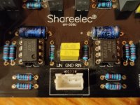
I have attached a couple of pictures of the amplifier board and its input stage. Near the input I believe we see the op amps for preamplification the manufacturer mentioned. I wonder, could one solution be tapping the circuit after the preamplification stage where it could hopefully have higher impedance?
A final note, this thing sounds fantastic but I always found it too damn loud. I have to lower the volume a lot on all of my sources for normal listening levels. This is why I suspect that bypassing the preamplifier could be the way to go.
Any info/ideas/suggestions are welcome. Thank you guys.


I have this LM3886 based amplifier board. I want to use a small passive mixer as a source for it. The thing is, the passive mixer has something like a 2KOhm output impedance, which is kind of high. So, thinking that I need at least 20KOhm input impedance at the amplifier input, I set out to find out what it actually is.
Checking the manufacturer's spec sheet did not mention input impedance. Upon inquiry, they mentioned that the amplifier has a preamplifier stage, and that its input impedance is 2.2KOhms.
Upon seeing this quite low number, I thought it was possible they didn't have a clue what they were talking about. So I set out to try to estimate it myself. I used the following video:
The trick is adjusting an external trim pot until the output amplitude is halved, then you can disconnect and measure your input resistance at the trim pot. The only thing I did differently was instead of using an oscilloscope to check output amplitude, I used a normal multimeter to measure AC rms voltage since I reckoned it's proportional to amplitude thus an equivalent measurement.
I used two test signals, one at 1KHz and one at 600Hz, of the same amplitude. Interestingly enough, my measurements for impedance with this method were 2.6KOhm @1KHz and 2.84KOhm @600Hz. The trick seems to at least yield higher impedance for lower frequencies and for certain the numbers are of the same order of magnitude as what the manufacturer claimed.
Now, supposing we have a source of about 2KHz output impedance, and an amplifier of about the same input impedance, what could I do to connect them without losing signal quality? I understand input impedance should be one order of magnitude higher.
I have attached a couple of pictures of the amplifier board and its input stage. Near the input I believe we see the op amps for preamplification the manufacturer mentioned. I wonder, could one solution be tapping the circuit after the preamplification stage where it could hopefully have higher impedance?
A final note, this thing sounds fantastic but I always found it too damn loud. I have to lower the volume a lot on all of my sources for normal listening levels. This is why I suspect that bypassing the preamplifier could be the way to go.
Any info/ideas/suggestions are welcome. Thank you guys.
Your method is good, but to be absolutely sure it needs to be done with the amp powered and at very small signal levels. That amp is sold in various places, Alibaba and others, but nowhere can I find a schematic of it. They use quite opaque solder masking, so it's hard to see the traces. Still, if you could work out a schematic of the front end, that would be useful. I can be done visually and also by measuring resistance from opamp pins to the various resistors to confirm.
Somebody said you should drive loads with a source of 10X the input impedance, but IMO this ignores a lot of things. If the load has a flat input impedance, and the source too, it doesn't matter. Even if you load the source so the output voltage is half, the response will still be flat. OTOH, if the impedance isn't flat with frequency, you could need more than 10X difference. It would be rare for any kind of opamp input buffer not to be flat. I'd probably try a simple two resistor voltage divider at the input and then measure the total response. I'd probably cheat and wire up a 5k or 10k pot as the divider, set my volume control at a reasonable position, then set the pot for the volume you want at that setting. Then I'd measure the side of the pot and replace it with resistors.
Somebody said you should drive loads with a source of 10X the input impedance, but IMO this ignores a lot of things. If the load has a flat input impedance, and the source too, it doesn't matter. Even if you load the source so the output voltage is half, the response will still be flat. OTOH, if the impedance isn't flat with frequency, you could need more than 10X difference. It would be rare for any kind of opamp input buffer not to be flat. I'd probably try a simple two resistor voltage divider at the input and then measure the total response. I'd probably cheat and wire up a 5k or 10k pot as the divider, set my volume control at a reasonable position, then set the pot for the volume you want at that setting. Then I'd measure the side of the pot and replace it with resistors.
I'm just guessing here, but the two resistors on the bottom are identical on both side, so I suspect it's a voltage divider to use as a bias to the opamp since it's a single supply.
The other resistors in the circuit appear to be 2.2k, 8.5k, and 20k, if I deciphered the codes correctly. So I would think the 2.2k is your input resistor, and the 20k/8.5k are forming the amplifier part of the opamp. That ratio of 20/8.5 is likely setting the gain.
The other resistors in the circuit appear to be 2.2k, 8.5k, and 20k, if I deciphered the codes correctly. So I would think the 2.2k is your input resistor, and the 20k/8.5k are forming the amplifier part of the opamp. That ratio of 20/8.5 is likely setting the gain.
Probably so, if it's a single supply circuit.
The single supply bias resistor (usually 100k or so) to ground needs bypassing to ground, at least 0.1uF,
but it's better to use around 10uF. Do you have a bypass cap there? Omitting it could cause some hum.
If the amplifier board input resistor to ground is really 2k, that might cause some potential problems
with the source feeding the amplifier. Around 10k is more typical to use.
Last edited:
Pictures alone are not enough.
We need a schematic, but at least post a direct link to the original page.
2k range input impedance is WAY too low for a general purpose amplifier.
That coupled to the excessive sensitivity makes me suspect a Microphone input.
We need a schematic, but at least post a direct link to the original page.
2k range input impedance is WAY too low for a general purpose amplifier.
That coupled to the excessive sensitivity makes me suspect a Microphone input.
The problem is exactly that, source output impedance and load input impedance are matched and this is an audio application.You only need to match impedances if its a transmission line and reflections aren't wanted.
For audio I would use 10x output impedance of pre amp as input impedance of power amp.
It's quite probable you're right, although it was not advertised as a mic preamp/amp. Indeed the impedances I've seen on mic inputs are typically in the 2KOhm to 3KOhm range.Pictures alone are not enough.
We need a schematic, but at least post a direct link to the original page.
2k range input impedance is WAY too low for a general purpose amplifier.
That coupled to the excessive sensitivity makes me suspect a Microphone input.
If it's any help, the power supply is dual AC. I feed it dual 25VAC with the transformer of an old mini stereo that ultimately died on me.Probably so, if it's a single supply circuit.
The single supply bias resistor (usually 100k or so) to ground needs bypassing to ground, at least 0.1uF,
but it's better to use around 10uF. Do you have a bypass cap there? Omitting it could cause some hum.
If the amplifier board input resistor to ground is really 2k, that might cause some potential problems
with the source feeding the amplifier. Around 10k is more typical to use.
Some specifications from the automated messages sent by the seller after my inquiry:
---
Power supply voltage: AC12-28V X 2 (double AC)
Power supply: recommended above 200W
Output power: 68W X 2 MAX.
Output impedance: 4-16 ohms
Channel: 2-channel stereo
Circuit architecture: LM3886+OPO7+NE5534
Features: Pre-stage stabilized DC servo with protection
Protection feature: overheating, DC short circuit protection
Size: 14.8*13.5*5cm
Net weight: 548.5g
Important hint:
1. The maximum power depends on the power supply voltage power and speaker impedance, THD = 0.1%, RL = 4Ω VS = ±28V;
2. If it is a 4Ω load, the voltage of the transformer should not exceed double AC20V to avoid unnecessary losses;
---
The most important concern is input impedance and a fix for that. Lowering sensitivity would be nice but not necessary as the passive mixer attenuates about 12dB.
I measured voltage on the speaker at low volume (the amp was turned on as you might guess). Value without external resistance was about 1.8VAC and I measured the series resistance at the input that brought it down to about 900mVAC. I think it was a valid measurement that matches what they told me the input impedance is.Your method is good, but to be absolutely sure it needs to be done with the amp powered and at very small signal levels. That amp is sold in various places, Alibaba and others, but nowhere can I find a schematic of it. They use quite opaque solder masking, so it's hard to see the traces. Still, if you could work out a schematic of the front end, that would be useful. I can be done visually and also by measuring resistance from opamp pins to the various resistors to confirm.
Somebody said you should drive loads with a source of 10X the input impedance, but IMO this ignores a lot of things. If the load has a flat input impedance, and the source too, it doesn't matter. Even if you load the source so the output voltage is half, the response will still be flat. OTOH, if the impedance isn't flat with frequency, you could need more than 10X difference. It would be rare for any kind of opamp input buffer not to be flat. I'd probably try a simple two resistor voltage divider at the input and then measure the total response. I'd probably cheat and wire up a 5k or 10k pot as the divider, set my volume control at a reasonable position, then set the pot for the volume you want at that setting. Then I'd measure the side of the pot and replace it with resistors.
I'm having trouble following your analysis of the necessary relationship between output impedance vs input impedance. I think I understand 10x is just a rough rule.
Are you saying that the input stage should almost certainly be flat impedance frequency wise so this allows me to just use a voltage divider at the input? If yes, what problem would that solve, low impedance or high sensitivity? Perhaps both?
Btw, my crude impedance measuring attempt showed impedance dropping with frequency. I don't know if this means that the input stage does not have a flat impedance frequency wise (so a voltage divider would not be ideal, if I understand everything correctly).
I'm afraid you won't get much wiser by the product page (plus I'm a bit concerned it would count as advertising) but here goes:Please post a direct link to that board, so we read what it says or see more pictures.
https://m.aliexpress.com/i/32839668129.html
If you need more detailed pictures let me know. Since I own the board and a multimeter, I would be glad if I could decode or even modify the input stage of the amp with you guys helping me out.
Oh, one mention, needed to clarify a doubt, should not count as "advertisement"
Not like other threads which have been mercilessly hijacked to push a pseudoscience snake oil brand")
There´s something weird here which makes me think:

Not clear at all , but MAYBE it means:
* CS-capacitor direct connection = from input pin straight to LM3886 (high impedance) input pin, nothing else on that track.
-or-
* OS .... Op Amp gets in the path, but an improperly placed jumper might connect input pin to Op Amp output or to some resistor "it shouldn´t" ... or ... or ... or ...
Your choice, personally I would lift a capacitor or something as needed and connect PCB input pin straight to LM3886 input pin.
That should restore both proper sensitivity and high input impedance.
Of course trace everything first to avoid mistakes or damage.
Not like other threads which have been mercilessly hijacked to push a pseudoscience snake oil brand
There´s something weird here which makes me think:
Not clear at all , but MAYBE it means:
* CS-capacitor direct connection = from input pin straight to LM3886 (high impedance) input pin, nothing else on that track.
-or-
* OS .... Op Amp gets in the path, but an improperly placed jumper might connect input pin to Op Amp output or to some resistor "it shouldn´t" ... or ... or ... or ...
Your choice, personally I would lift a capacitor or something as needed and connect PCB input pin straight to LM3886 input pin.
That should restore both proper sensitivity and high input impedance.
Of course trace everything first to avoid mistakes or damage.
Apparently you did become wiser after examining the product page. They mention buffering so it may well change the input stage behavior drastically. The big question is, what mode is my board at the moment, and how to switch to the other mode if it offers higher impedance and/or lower gain. I contacted the seller about this but I'm afraid it's going to be a long wait...Oh, one mention, needed to clarify a doubt, should not count as "advertisement"
Not like other threads which have been mercilessly hijacked to push a pseudoscience snake oil brand
There´s something weird here which makes me think:
Not clear at all , but MAYBE it means:
* CS-capacitor direct connection = from input pin straight to LM3886 (high impedance) input pin, nothing else on that track.
-or-
* OS .... Op Amp gets in the path, but an improperly placed jumper might connect input pin to Op Amp output or to some resistor "it shouldn´t" ... or ... or ... or ...
Your choice, personally I would lift a capacitor or something as needed and connect PCB input pin straight to LM3886 input pin.
That should restore both proper sensitivity and high input impedance.
Of course trace everything first to avoid mistakes or damage.
It seems you're good at eyeballing stuff, so I bet you recognize this (unknown to me) wiring of the op amps with a resistor/capacitor network. I presume this is a very standard circuit. Could you (or any other forumer willing to) point me to a schematic that closely matches the circuit at hand? I think it would be a great idea trying to understand this first input stage of the amp.I'm just guessing here, but the two resistors on the bottom are identical on both side, so I suspect it's a voltage divider to use as a bias to the opamp since it's a single supply.
The other resistors in the circuit appear to be 2.2k, 8.5k, and 20k, if I deciphered the codes correctly. So I would think the 2.2k is your input resistor, and the 20k/8.5k are forming the amplifier part of the opamp. That ratio of 20/8.5 is likely setting the gain.
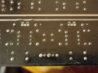
The second picture I attached to this post, shows the bottom "jumper" pins. Until I get a response from the seller, I have no clue how to use them to change operating mode as described in the previous post. But I can tell for sure that the innermost pins are permanently connected to the innermost pins of the blue horizontal capacitors at the top, if that is at all useful info.
Attachments
Pictures alone are not enough.
We need a schematic, but at least post a direct link to the original page.
2k range input impedance is WAY too low for a general purpose amplifier.
That coupled to the excessive sensitivity makes me suspect a Microphone input.
So I sat down and (hopefully) traced most of the right side of the input stage:
These are the connections I traced with my multimeter. Hopefully squares and diamonds work better than adding lines to the picture. There are also measurements for resistors and capacitors although I do not trust the capacitance measurements too much, especially the top horizontal capacitor (PCB is marked 4.7U at that point).
I have asked the seller which configuration (OS or CS) my board is at right now. They replied neither, so apparently the board can be in one of three possible configurations. I asked them how each of the OS, CS modes is applied, and I am awaiting a response. Although they said they do not recommend the change to either one, I don't know why.
I'm currently guessing the configuration mechanism is soldering the two left most pins on the board, or soldering the two right most pins like this:
This is what I sent them to verify the mode selection mechanism. But I don't know if given the above diagram something might blow up this way.
Just by looking at the diagram with my inexperienced eyes does give me some hints. The two caps to the right are probably stabilizing power to the op amp that comes from somewhere outside the picture. Earlier in the thread, a member mentioned I can replace input resistors to increase impedance (hopefully in a clean manner). Signal goes through a 2.2KΩ resistor then right into IN+ of the NE5534, so that's clearly a candidate for replacement. I have no clue where IN- input comes from however, or what other resistor I have to change if I change the one that goes to IN+.
I am guessing the output of this stage is pin B of the top capacitor, although I could not trace where it goes after this stage.
Any comments on what might happen if I solder the left or right pair of contacts? A reminder that the descriptions are:
OS: "Op-amp used for a buffer"
CS: "Capacitor direct connection"
Do these make more sense after the connections shown on the PCB?
"What does this button do?" - Bruce Dickinson
Last edited:
Hey, so what is it you'd like to accomplish? Can you possibly redraw this as a schematic? Problem is you can measure continuity through components too, so it's probably distorting slightly what you think is connected.
The last thing I'd want to do is kill your amp, but if it was my amp I'd be playing around with it a bit.. I suspect if you take a resistor, like a 10k, and put in in parallel with the 55k one (touch both legs of the new resistor to both legs of the soldered one), it'll reduce the gain..
The last thing I'd want to do is kill your amp, but if it was my amp I'd be playing around with it a bit.. I suspect if you take a resistor, like a 10k, and put in in parallel with the 55k one (touch both legs of the new resistor to both legs of the soldered one), it'll reduce the gain..
- Home
- Amplifiers
- Solid State
- LM3886 amplifier input impedance