Synesthesia said:Really though, when I connect the negative wire to the negative end of the capacitor it becomes really hot. Is it possible that capacitors use a different system then what I learned in school? I was taught that the negative end gives off the electrons and the positive receives. Could capacitors go by the positive emits electrons and the negative receives?
No, no, no! Don't put the caps in the wrong way. The caps should stay cold. If they become hot, either the voltage limit of the cap (having a lapsus, I can't remember the word in english) is too low or you connected the cap in the wrong way. Minus goes to minus, plus goes to plus. Look closely on the cap, the marked pin isn't always the minus. If you put it in the other way you can get a very unpleasant explosion which can really hurt you. The voltage drop can be caused by this. It happened to me many times due to polarity reverse by mistake.
Synesthesia
I recommend you to go back to Nuuks informative site, for some more time until you really understand the basics.
You have mentioned several times that your transformer doesn't have a "ground" wire.And you also questioned why all the transformers simply can't have two input and two output wires.
You are so close to solving the problem there(I suppose).
Your transformer has 12.6-0-12.6Vac secundaries.When rectified you are supposed to get aproximately 18-0-18Vdc.
When you make the dual supply PSU,you will have +18,0,-18.The zero there,the third wire is your power ground.
So, you can see the three wires are needed.(Or a transformer with four wires,or two transformers with two wires.) but you have a transformer with three wires so let's concentrate on that.
If you have understood all this,great,forget my post.If not ,more study is needed to keep you alive and the house not burned down .
.
Good luck,I hope you get the amp working !
I recommend you to go back to Nuuks informative site, for some more time until you really understand the basics.
You have mentioned several times that your transformer doesn't have a "ground" wire.And you also questioned why all the transformers simply can't have two input and two output wires.
You are so close to solving the problem there(I suppose).
Your transformer has 12.6-0-12.6Vac secundaries.When rectified you are supposed to get aproximately 18-0-18Vdc.
When you make the dual supply PSU,you will have +18,0,-18.The zero there,the third wire is your power ground.
So, you can see the three wires are needed.(Or a transformer with four wires,or two transformers with two wires.) but you have a transformer with three wires so let's concentrate on that.
If you have understood all this,great,forget my post.If not ,more study is needed to keep you alive and the house not burned down
.Good luck,I hope you get the amp working !
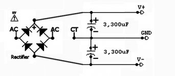
And be aware of the potentials. The cap with (-) at V- connects with (+) to ground. The cap with (+) at V+ connects with (-) to ground.ratza said:No, no, no! Don't put the caps in the wrong way. The caps should stay cold. If they become hot, either the voltage limit of the cap (having a lapsus, I can't remember the word in english) is too low or you connected the cap in the wrong way. Minus goes to minus, plus goes to plus.
Maybe it is easier, if you imagine that you are building two separate DC supplies. And when they are finished you stack them (electrically) on top of each other, i. e. V(+) of one supply connects to V(-) of the other and that connection is at the same time your ground potential.
Five wires is normal for the average center tap transformer.
It will have two wires seperated by a distance, and those are the ac input.
It will have 3 wires grouped together and that is the ac output.
One of the three output wires is different than the rest or somehow "marked" as the Zero Volt line. If in doubt, check the manufacturer's on-line documentation, probably in PDF format.
That is a VERY important wire because it will attached to the "power star ground" from which comes the system's ground as a reference.
And, have a look at this photograph (click the photo to enlarge):
Attachments
not necessary.danielwritesbac said:Five wires is normal for the average center tap transformer.
It will have two wires separated by a distance, and those are the ac input.
It will have 3 wires grouped together and that is the ac output.
It depends on how the manufacturer has grouped the tappings.
115+115:LV-0-LV is most common and has 7wires, but the physical spacing is no clue to which are which.
A safer way to go about things if no colour coded datasheet exists is to feed the transfomer from the AC of a low voltage transformer and do the calculations required to figure the stepping of the secondaries...
I think also use Andrew's lightbulb limiter.
I think also use Andrew's lightbulb limiter.
A nightmare scenerio is illustrated with the combination of the visually confusing, poorly-marked MUR860 diodes, eight of those in a dual rectifier to support a dual secondaries transformer, and a toroid transformer reliant on a color coded decal with an abbreviated note to decipher the tangle of wires. That popularized combination is seriously inappropriate for beginners. Of the many who have survived the illogical choice and then posted questions, one has to wonder how many have not.
Instead of promoting the most risk, why don't we promote the least risk?
Decreased risk:
1). The transformer has as few connections as possible, as clearly marked as possible--For LM3875, in the U.S. this is the 5 wire center tap, EI core, square transformer. Elsewhere, the EI core center tap transformer still helps in reducing the number of wires, they are still arranged in a logical manner, and this reduces confusion. Less confusion = less risk.
Example: http://www.partsexpress.com/pe/showdetl.cfm?&Partnumber=120-225
2). The rectifier is a plastic block, prefab 1-piece model--all connections are clearly marked and ready to use. Certain polarity markings = decreased risk.
Example: http://www.partsexpress.com/pe/showdetl.cfm?&Partnumber=050-030
3). The amplifier enclosure is wooden--absence of a large voltage reference surface makes for absence of the risks of a large voltage reference surface. This doesn't mean zero-risk, but an insulator, wood, is less-risky than a conductor, metal.
Example: http://www.lowes.com to make your own, or http://www.hobbylobby.com for prefab.
4). Lower voltage at the test bench/workspace--at testing time, a lower voltage transformer can be used to verify correct operation of the project. Decreased voltage = decreased risk.
Example: http://www.partsexpress.com/pe/showdetl.cfm?&Partnumber=129-035
This post is an attempt to relate an amplifier project to an audience accostomed to speaker building, and thus a popular (familiar) speaker driver vendor is quoted for the electronic supplies. On that note, the amplifier needs a "dual ported" enclosure, like cool air vent at the bottom (under the heatsink) and hot air vent at the top (or top of the rear panel).
Also, follow Andrew T's "double size" heatsink suggestions, because the price of a too-large heatsink is more affordable than the cost of a too-small heatsink.
What are the benefits between a 2 diode rectifier approach (one on + and one on -) and a bridge rectifier (4 diodes)?
the two diodes are a full wave rectifier.
the Bridge ensures the transformer is equally loaded in both windings and is more efficient in delivering full power, except for the extra 700mV diode loss.
There is a third option, two bridges, one across each secondary and then series coupled on the DC side.
the Bridge ensures the transformer is equally loaded in both windings and is more efficient in delivering full power, except for the extra 700mV diode loss.
There is a third option, two bridges, one across each secondary and then series coupled on the DC side.
- Status
- Not open for further replies.
- Home
- Amplifiers
- Chip Amps
- LM3875 issues