Can anybody please post some feedback on this layout based on Thorsten's LM3875 inverted schematic posted here:
http://home.attbi.com/~greggbaker/invertedLM3875.gif
I would really appreciate comments on what should be the proper grounding layout....
The jpg is not to scale. The actual size is 92.5mmx40.5mm
Thanks in advance.
http://home.attbi.com/~greggbaker/invertedLM3875.gif
I would really appreciate comments on what should be the proper grounding layout....
The jpg is not to scale. The actual size is 92.5mmx40.5mm
Thanks in advance.
Attachments
pad separation
it would appear that the pad separation is a little close on a couple of the LM3875 pins. As some of the pins are not connected to anything I just snip them off -- they really aren't needed for support. I have enclosed an updated snapshot of the PCB design which I use. The connector is a PC-power type. The image below is a little pixilated due to resizing, for a better image go to www.tech-diy.com/LM3875.gif
it would appear that the pad separation is a little close on a couple of the LM3875 pins. As some of the pins are not connected to anything I just snip them off -- they really aren't needed for support. I have enclosed an updated snapshot of the PCB design which I use. The connector is a PC-power type. The image below is a little pixilated due to resizing, for a better image go to www.tech-diy.com/LM3875.gif
Attachments
Pins
In fact pins 2, 5, 6, 9, 10 and 11 are not connected on the 3875, so I think they can be snipped off.
One thing I was not aware of on the 3886 I was oing to use, is that the mute has to be conneced through a resistor and not left open, as I thought it should be.
Jackinnj: what program did you use for your pcb? and where are the resistors?
Ppereira: have you shown your pcb design at the gainclone site?
Carlos
jackinnj said:it would appear that the pad separation is a little close on a couple of the LM3875 pins. As some of the pins are not connected to anything I just snip them off -- they really aren't needed for support.
In fact pins 2, 5, 6, 9, 10 and 11 are not connected on the 3875, so I think they can be snipped off.
One thing I was not aware of on the 3886 I was oing to use, is that the mute has to be conneced through a resistor and not left open, as I thought it should be.
Jackinnj: what program did you use for your pcb? and where are the resistors?
Ppereira: have you shown your pcb design at the gainclone site?
Carlos
Assembly
One thing I forgot to say is that if you snip the pins off, you should provide some way to secure the pcb and heatsink together. And only solder the pins after pcb, heatsink and chip are all bolted to their respective surfaces.
This is also valid if you leave all the pins.
If you don't take such precautions you may have future problems. Intermittents probably, which are the worst.
Carlos
Carlmart -- I use Ultiboard -- the 700 pin version (if anyone want's to know how to bootleg more pins just create two circuits being careful of the board layout -- then merge the two text files containing the plotter code).
The feedback resistor and compensation network are on the bottom side of the board --
The feedback resistor and compensation network are on the bottom side of the board --
Carlos,
I posted it here first because there is a wider variety of experienced people in this forum. My problems so far with Opamp based amplifiers revolve around grounding noise. I was hoping that somebody could pinpoint where I am making the mistakes that I am sure I am making 🙂
Jackinnj,
Thanks for your comment. I will remove the unused pins. Nice layout. It's based on the same schematic as mine, right?
C
CryingDragon
jackinnj said:Carlmart -- I use Ultiboard -- the 700 pin version (if anyone want's to know how to bootleg more pins just create two circuits being careful of the board layout -- then merge the two text files containing the plotter code).
The feedback resistor and compensation network are on the bottom side of the board --
you bastich! right now i'm limited to 100 with labcenter electronics ARES lite....700 to me would be more than i could use 🙂
yupp, same schematic
I don't think that you need to use an expensive cap in the compensation loop -- I got mine from Mouser. the THD measures around 0.01% to 0.04% -- not bad for a couple bucks.
I don't think that you need to use an expensive cap in the compensation loop -- I got mine from Mouser. the THD measures around 0.01% to 0.04% -- not bad for a couple bucks.
How does your setup sound? Do you hear any noise (static) coming from the speakers when idle? That's my problem right now using a non-inverted "gainclonish" schematic... I assume it's a grounding problem because the noise is slightly louder when I turn the volume all the way down... (dact stepped attenuator 20k)
I am using the auricaps because I just happen to have a few laying around... 🙂
I am using the auricaps because I just happen to have a few laying around... 🙂
A big power opamp, huh?
Interesting thread.
I hope this question isn't too naive (I'm into tubes, not SS), but has anyone tried what most folks first do to get better sound out of an opamp: biasing the output into class A?
As the supply rails are loosely regulated, a true CCS should be used and not a simple resistor to the negative rail.
The LM3875 is called a "quasi-class AB" amp, so I hope that it will take pulling into a little deeper class A.
Any opinions on what current values to try?
Thanks all,
Steve Jones
Re: A big power opamp, huh?
I don't see a resistor to replace on the negative rail. Where are you putting the CCS?
This amp is so simple i don't know why you would be bothered with a circuit board at all. Dead bug style has the potential to sound better.
dave
steve jones said:As the supply rails are loosely regulated, a true CCS should be used and not a simple resistor to the negative rail.
I don't see a resistor to replace on the negative rail. Where are you putting the CCS?
This amp is so simple i don't know why you would be bothered with a circuit board at all. Dead bug style has the potential to sound better.
dave
Re: Re: A big power opamp, huh?
I second that too. More info http://www.diyaudio.com/forums/showthread.php?s=&threadid=4999&highlight=lm3875
planet10 said:
This amp is so simple i don't know why you would be bothered with a circuit board at all. Dead bug style has the potential to sound better.
I second that too. More info http://www.diyaudio.com/forums/showthread.php?s=&threadid=4999&highlight=lm3875
resistors - on the bottom
the RC network and feedback resistor are on the bottom of the board -- that's why it all fits
the RC network and feedback resistor are on the bottom of the board -- that's why it all fits
"I don't see a resistor to replace on the negative rail. Where are you putting the CCS?"
No resistor to replace.
Just wondering if one could add a CCS, instead of a simply adding a resistor (as is usually/easily done with opamps), to bias the output deeper into class A.
The Gainclone designs I've seen and the datasheets for the LM3875 don't seem to have have an output current draw at idle.
Wondering if anyone has tried it, or even if it is practical with this big "opamp".
Steve
steve jones said:The Gainclone designs I've seen and the datasheets for the LM3875 don't seem to have have an output current draw at idle.
Someone on the DIY amp chip forum estimates 70 mA.
dave
planet10 said:
That's the supply draw (Total Quiesient Power Supply Draw) or "I+" on the datasheet. This is at idle with a common mode input (pins 7,8) of "Vcm=0", voltage out (pin 3 to gnd) "Vo=0", and current out (pin 3 to gnd) "Io=0".
By adding a current sink from output (pin 3) to the negative rail, more current will be drawn by the positive output transistors, and should bias the output into deeper class A. Albeit at a higher heat and lower power output. But being held longer in class A, it *should* sound *better*.
Its been done for decades to conventional opamps, to tweek the sound of a circuit. Just wondering if it could be done with the LM3875.
Guess I'm going to have to try it.
Steve Jones
I just used the LM3886 in non-inverting configuration with deadbug wiring. I used a very low closed loop gain of 12. By keeping the feedback network at very low resistance (3k3 over 300), I did not need any compensation caps in parallel to the feedback resistor), nor did I need a Zobel load at the output. A 10-turn coil on the output was all that was needed to make it stable with any capacitive load.
As the volume pot in a typical listening setting has about 300 R resistance, the impedances on the two inputs are approximately balanced, so I needed neither coupling cap nor feedback coupling cap. DC offset measured 0 - 15 mV, depending on volume setting.
I wired the ground return for the supply caps (2x1000 uF Panasonic FC and 2x470 nF Wima MKS2) close to the pins to the ground speaker output terminal, twisting this ground cable and the output cable together. The speaker terminal ground of course has a return to the star ground. The signal/feedback ground has a separate connection to the star ground.
The idea behind this is that the current to the speaker gets drawn from the supply caps and the return is just through the ground connection of these caps so connecting them to the signal ground is not a good idea. Twisting the cables together minizmes the loop area for the load current.
Sound was amazing for such a simple amp. Compared to my big amp, it was maybe a little too polite and lacked a little clarity and dynamics.
Eric
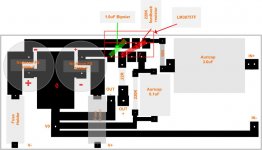
My layout...
Hi folks,
below is the layout I use, still in the test stage tho, and up for improvements!
What caps are people using for the 1uf, mine is a polystyrene, do bipolars sound ok?
I have just used normal star grounding, and have a little hum with volume at max, perhaps for the next iteration I will try Eric's ideas and see if that is better
Attachments
- Status
- Not open for further replies.
- Home
- Amplifiers
- Chip Amps
- LM3875 Inverted Layout Comments Please