Although there is no evidence to support it, I want to believe that the LM3875 makes a decent headphone amplifier. It almost does as a standard gainclone, but the unregulated supply is just a wee bit noisy.
The case for: plenty of current reserves, designed to drive even lower loads than headphones with minimal distortion. Stable, easy to work with.
So, I figure, when not treat the LM3875 as you would any other op-amp in a headphone circuit: add in regulated supplies, and run it off 12 or 15V rails. (datasheet minimum is 10V)
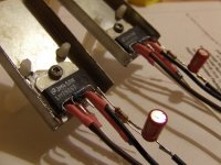
This is a standard non-invering circuit, with no input coupling cap (might add it?). Simple as can be. PCB is 2"x1.4"
No clue if this is a good idea or a bad one, but I thought I'd share it.
/rjm
The case for: plenty of current reserves, designed to drive even lower loads than headphones with minimal distortion. Stable, easy to work with.
So, I figure, when not treat the LM3875 as you would any other op-amp in a headphone circuit: add in regulated supplies, and run it off 12 or 15V rails. (datasheet minimum is 10V)
This is a standard non-invering circuit, with no input coupling cap (might add it?). Simple as can be. PCB is 2"x1.4"
No clue if this is a good idea or a bad one, but I thought I'd share it.
/rjm
Attachments
I tried a regular amp's version as a headphone amp and it works pretty well, better than Benchmark used in the same application. It is especially good with AKG K1000, as you can read here: http://www.6moons.com/audioreviews/audiooasis/audiozone_3.html
The K-1000s aren't really a good example of a "typical" headphone... not too surprising a LM3875 based amp works well with them. I wonder if the LM3875 would still be a good choice when the load impedance and sensitivity start climbing into Sennheiser HD600 territory. My concern is how much noisier the chip is compared to typical audio op-amps. Let's try to figure that one out:
From the datasheet, you can guestimate that the THD+N at 10mW into 8ohms (26dB gain test circuit, 80kHz bandwidth) is 0.1%. This, one can safely assume, is almost entirely noise... the N part of THD+N.
The output voltage at 10mW/8ohms is: 283 mV.
The input voltage at stated gain 20x is: 14 mV.
0.1% of this is 14 uV.
Divided by sqrt of 80kHz, the e_n is 50 nV/sqrtHz
The input referred voltage noise (e_n) of the LM3875 is 50nV/sqrtHz about 10 times (20dB) higher than a typical audio op-amp. It comes down to whether a 20dB increase in noise is a price worth paying for the (presumably) lower distortion.
The output voltage for headphones is about 10 or 20 dB lower than loudpeakers. So the amplifier noise will be that much more more "apparent".
/r
I wonder if the LM3875 would still be a good choice when the load impedance and sensitivity start climbing into Sennheiser HD600 territory
How would i find this out? Build the circuit i suppose- could anyone suggest cap/resistor values.
BTW thanks Richard for starting this.
I have thought about using the LM1875 ,LM3875, LM3886 etc to use as a headphone amp too. I think I actually tried it once but I cann't teally remember. My first motivation was that the those power-chip-amp would probbably stay well the in Class A region when used as a headphone amp.
Concerniong the noise: I really don't think that is an issue. If the dynamic range is good enough for speaker, it probbably will be good enough for headphones.
50nV/sqrt(Hz) gives 109 dB S/N when the max input signal is 2Volt. Offcourse then you need to build a normal highes voltage version with a attenuator resistor network at the output to acomplish that.
goodluck,
Thijs
edit
To me the voltage regulator really aren't nessecery; my speakers are completely hum free. What's good enough for speakers, will be good enough for headphones provided a attenuator netwerk is used out the output.. say.. 680R-out-33R--GND
I also tried AMP-1 with both Senns HD650 and Grado RS-1 and it worked fine. Hard to say how good, as I don't have any real reference headphone amp (but will have soon for comparison).
If you are actually building a n.i. Gainclone-type circuit from scratch just for headphones, I suggest lowering the gain from 30x down to 10x, by reducing the feedback resistor from 22k to 6.8k. Everything else can be the same, though an output series resistance of 120 ohms or so (see next paragraph) can be added.
An attenuator (resistor) at the output will indeed improve the signal to noise. However, I'm not too sure that a values above 120ohms are such a good idea. The load impedance of headphones is relatively flat, but still... on the other hand it could be just the ticket - what do I know? The correct value can be easily found by trial and error.
If you want to listen to headphones with a standard chip amp (Gainclone or otherwise), then the series resistance can be easily added as part of a wiring circuit connecting the output to the headphone jack. Add another pole to the mute switch, and you have a speaker/mute/phone switch. Very professional!
It may well be that the internal amplifier noise is greater than the output noise caused by the power supply, even when unregulated. If thats the case adding voltage regulators wont make any difference to the output noise.
Has anyone compared the noise of a Gainclone powered by regulated vs. unregulated supplies, or batteries vs. unregulated supplies?
-R
Test results
Tried the Grado SR60 and Sennheiser HD600 with my gainclone, thorugh 100 ohm resistors. From the computer CD-ROM, I tested the line out directly into headphones, line out into the gainclone, and digital optical out through a NonOS TDA1543 DAC to the gainclone.
With the inputs left open, volume turned to max, and the gainclone case grounded, there was absolutely no audible noise with either of the headphones tested. As in "is the power on?".
The Grados cause the computer output to distort. They dont sound terrible even then, but for clean sound a separate amplifier is needed. Unfortunately, with the Gainclone, the sound was a little dull, as if rolled off in the treble. My guess is 100 ohms series resistance is too high a value for these 32 ohm cans.
The Sennheisers work quite well from the computer output directly, and to be honest putting the gainclone in the chain didn't make much difference. In either case the limitations of the source were obvious. The HD600s made clear the benefits of using the external DAC, but at the same time showed up the limitations of that component, too, as the DACs noise floor was considerably higher than the gainclones.
So I can confirm Peter Daniel's original assessment that the Gainclone works quite well both high and low impedance headphones. No need to add regulated supplies, or even change the gain. I doubt that even the output series resistance is needed.
The gainclone as a headphone amplifier seems to sound pretty much the same as the gainclone as a loudspeaker amplifier. Mine sounds a little dark, a little closed in. Always has done. Overall though it neither adds, nor subtracts, much from the source.
-R
Mind you that I did not suggest a series resistor, but a attenuator network! This way you can create any output resistance you want. I would suggest a 600R-33R-GND network, and take the output from the top of the 33R resistor to GND. This give about 30R output resistance and -26dB attenuation. So you do not need to change the gain of the amp, and you get about the same S/N.
good luck,
Thijs
good luck,
Thijs
The only difference is the additional resistance to ground, which does I admit have a the benefit of making the attenuation less dependent on the headphone impedance. Still, in my view -26dB isn't necessary. -6 to -10dB should be enough, taken either at the output, the input, or the feedback loop.
Adding a crossfeed filter somewhere should nicely bring the attenuation down, and be a welcome feature besides.
Ultimately it must be said that I dont much like listening to headphones, even though objectively the HD600s sound very nice. I suspect I suffer more than most people from the disorientation caused by the blobs-in-the-ear effect. So while what I heard through the gainclone was perfectly acceptible, it didnt really have me jumping for joy... and I doubt it was significantly better than a well built ChuMoy.
The only headphone amp I could dig was (my modded version of) the Szekeres SE MOSFET design, both archived at headwize. It had enough treble roll off and added 2nd harmonics to compensate for the in the ear thinness of headphone sound. A decent amount of crosstalk probably helped, too.
I guess what Im trying to say is if heaphone amps float your boat the LM3875 is a hi-fi option, especially for low impedance cans. Hi-fi by itself, however, doesn't do it for me when it comes to headphone listening. Sadly, "Faking it" is probably more important.
-R
hi, if i want to make headphone amp..what else do i have to buy beside the LM3875 dual mono kit?
i saw in the kit instruction user manual, each pcb consisting the opamp is connected to L&R RCA. how should i connect if i want to have a 6.3mm headphone out?
and i also want 1 set of L&R RCA input channel. sorry for the noob questions.. 😀
i saw in the kit instruction user manual, each pcb consisting the opamp is connected to L&R RCA. how should i connect if i want to have a 6.3mm headphone out?
and i also want 1 set of L&R RCA input channel. sorry for the noob questions.. 😀
Sorry to dredge up an old thread but I thought this more correct than starting a new one...
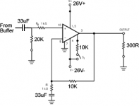
I spent all of yesterday adding a headphone section to my DIY preamp (which is based on Pedja Rogic buffer circuit). I used a pair of LM3886 on tiny heatsinks running off a nice transformer of 17 - 0 - 17 @1A (26VDC+-). I used non-inverting configuration using 1K to ground with 33uF cap and 10K feedback resistor. I used a 1K input resistor and 20K to ground (for extra protection against the deadly floating input).
At first I noticed 40mVDC on the outputs so I added a DC blocking cap on the input. There's now basically zero DC offset but I *am* a bit concerned that if I get a fault condition my HD600 'phones will be fried instantly. Should I add DC blocking to the output or will it wreck the sound?
The sound? Well I don't own a headphone amp so have nothing valid to compare this to but it sounds great to me running off a test cd player (lightly modified Marantz CD52). After more testing I'll get it in the system running off my FULLY modified Arcam Alpha (TDA1541) player. The sound is I suppose quite dark with great bass and dynamics and is fairly open and harshness-free. You can, of course, just keep going higher with the volume. I did a rough calculation showing max output into these 'phones is probably about 1W if accidentally turned up full. I'm sure it could break them but it's unlikely to happen by mistake.
I don't really like the idea of using output resistors as I expect it would harm the sonics, but is there something real to be gained there?
My test headphones (Creative ear buds) show huge hum and noise which is inaudible through the Sennheisers so I'm not sure what to make of that. The discrepancy is enormous though.
Just wanted to share this little project, which took me about 14hrs non-stop yesterday!
Simon
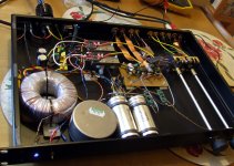
Attachments

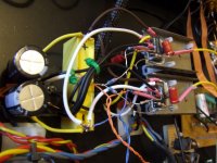
I wired up the muting circuit using 10K resistors which are joined together and then feed the switch that connects them to -Ve. Tagged off this is a blue LED (via 4 x 1.2K resistors in series [to stay cool]) to indicate the 'phones are unmuted. You toggle the switch to mute and the light goes out, I'm well pleased with that lol.
So far I've not used any bypass caps, which I realise is not really ideal, though the psu leads are short. The PSU is a big packaged bridge, cheap 1800uF Nichicons, bypassed with a 10uF film cap per rail.
The tiny steel heatsinks get very hot (you can just about keep a finger on) but are no hotter after 30mins than 2mins so I think it's perfectly safe. I didn't realise the LM3886 could get so warm at idle - just maybe I have an issue like oscillation - any opinions? Is the gain too low?
Thanks for looking and I'd appreciate any opinions from chip amp aficionados or headphone users, particularly if I've done something stupid.
Thanks,
Simon
the gain is almost at the minimum that National recommend.
I think you would see quite a bit of overshoot on faster signals when so much of the signal is fed back.
The reduced feedback when using gains set to between 25 to 30times gives more accurate reproduction of the input signal.
This is why many builders say they prefer a gain of 28times to other gains they have compared.
It is just possible that you may have some oscillation. Have you scoped the output?
How loud is the noise when feeding headphones? I would expect 95dB/mW headphones to show up noise much more than 95dB/W speakers
The 33uF input cap is completely mismatched to the 33uF NFB cap.
3.3uF input and 100uF NFB should sound quite different. You would need to experiment to find which is nicer.
Andrew,
Thanks for your useful input. National say a gain of 20 is normal but I can't see a minimum. I think it's well-known the chip is not supposed to run at unity gain and I sort of guessed ~10 would be a fair compromise between stability and being too loud and noisy (gaining only to attenuate). As this works quite well I could try a slightly higher gain and still have some use of my volume control. To mitigate the volume range issue I could attenuate the input a little more..
I've not scoped the output as I don't have a scope handy, nor do I know how to use one.
The background noise is very low on my Sennheiser HD600s and very loud and clear on cheap nasty headphones. On my Senns I hear just a touch of hum with no music playing and the noise of the source (CDP with Class A FET output stage - quite noisy itself).
If I use an input cap can I disregard/remove the NFB cap? I have some CHEAP 10uF film caps I could use on the input. I may just try this as it may sound better than the Black Gate Nonpolars I'm using.
I've put this amp into my system now and listened to a couple of CDs from my proper CD player. It does indeed sound excellent. I'm quite sure it would disgrace various standalone headphone amps, at least when running these Sennheisers. That's not to say the sound is perfect, it isn't. But then, is headphone listening ever very good??
- Status
- Not open for further replies.
- Home
- Amplifiers
- Headphone Systems
- LM3875 as a headphone amp (another try)