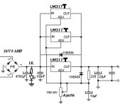
Hi, I am looking at schematic from the LM317 datasheet:

But can I just implement that and run it?
I miss a lot of details - what is the 0.2 ohm power rating, where are the flyback protection diodes for LM317, is the opamp some current limiter and if so, how do we set the current limit (i guess it is set to 4 amps).
Any major drawbacks for this schematic? Going for LM317 in parallel,because I do not need a lot of current, the layout is simple and parts laying around.
Power consumption ~2.5A/ 20v.
Plan to use it for a laptop. The original psu and the replacement one stopped working, so I am fed up with smpsu's
The laptop is going to be a mediaplayer, so noise and hum is an issue.
Regards

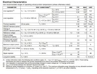
Generally LM317 needs at least 3V and for low ripple 4V of overhead so there will be fair amount of heat on those LM's
0.5 watt or higher.what is the 0.2 ohm power rating
Does the LM317 actually need them? I suspect not here.where are the flyback protection diodes for LM317
Current limit is set by the LM317 itself, so 1A per reg approx. Thr opamp is used for setting the voltage.is the opamp some current limiter and if so, how do we set the current limit (i guess it is set to 4 amps).
Don't blame a reputable SMPS if there are problems, something else is happening if you have issues. A good and suitably specified SMPS is absolutely the best option here. Don't under estimate how hot the linear regs will get. If you draw 3A @20v and have 25v input you have 15 watts of heat to dissipate plus that of the transformer and diode pack.Plan to use it for a laptop. The original psu and the replacement one stopped working, so I am fed up with smpsu's
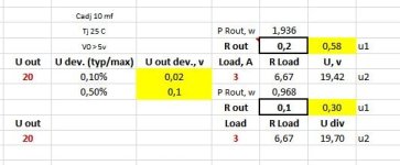
An LM317 current limit is about 2.2A so the 0.2 Ohm resistors don't need to be larger than 2.2*2.2*0.2= 0.968 x2 for margin = 2 Watts
The op-amp is voltage feedback so that Vout /2 (5K/10K) is equal to (3*Iadj+1.25V/100 )* (150+0 to 1500), ie Vout ~= 4.5 to 25V. Actually, the range is more than that. I should think the vendors has tested the circuit, but I see no decoupling caps or protection diode.
LM317 are linear regulators that will need a big heat sink.
I guess, the original smps was as reputable as for the eastern european market (probably crap).Don't blame a reputable SMPS if there are problems, something else is happening if you have issues. A good and suitably specified SMPS is absolutely the best option here. Don't under estimate how hot the linear regs will get. If you draw 3A @20v and have 25v input you have 15 watts of heat to dissipate plus that of the transformer and diode pack.
The laptop is a chinese made Lenovo
What is the advantage of the opamp + extra transistor, compared to this simpler schematic:
- https://powersupply33.com/power-supply-4-5-a-with-3-lm317-in-parallel.html
The latter does have a protection diode, and does not have resistors at the LM317 outputs....
- https://powersupply33.com/power-supply-4-5-a-with-3-lm317-in-parallel.html
The latter does have a protection diode, and does not have resistors at the LM317 outputs....
Attachments
The diodes only come into play if a reverse bias situation actually occurs (usually as rails initial build up and also discharge at switch on and off) and that is usually application specific such as using regulators on split rail supplies. Given the simplicity and cost then if you have doubts just add them.

I'm not sure that circuit is well thought out. Paralleling semiconductors directly usually doesn't work because of minute differences in the tolerances. If one reg produces 20.05 volts and another 19.98 then the higher voltage one will try and provide all the current. That is the reason for the 0.22 ohm resistors in the other option.What is the advantage of the opamp + extra transistor, compared to this simpler schematic:
👍 I should have checked a data sheet. Looks like 1.5A is a mentioned 'guaranteed' figure provided you keep it cool enough. This is for T03 and T0220 packages.An LM317 current limit is about 2.2A so the 0.2 Ohm resistors don't need to be larger than 2.2*2.2*0.2= 0.968 x2 for margin = 2 Watts
Oks, but what is the advantage of the extra opamp and transistor?
(the TI datasheet schematic)
- better voltage regulation, more precise current limiting/ protection of the circuit, lower noise...
And how about the 0.2 ohm value... If we 'just pick' 0.1 ohm, the resistors might be smaller
(the TI datasheet schematic)
- better voltage regulation, more precise current limiting/ protection of the circuit, lower noise...
And how about the 0.2 ohm value... If we 'just pick' 0.1 ohm, the resistors might be smaller
These LT regulators are better, and it's easier to do with one regulator than with three and an OPA. You also have ready-made PCBs for them on eBay.
One of the main reasons to use a paralleled regulator or, more often, a pass transistor is for increased power handling - multiple packages are capable of dissipating more power than a single. While there are some benefits for using multiple regulators over a pass element, the largest benefit is to the manufacturer who sells more expensive regulators as opposed to a cheap pass device 😉
Given the circuit is from the data sheet you have to take it that it gives the best performance. Using an opamp for feedback will likely improve regulation etc but tbh non of this matter for a laptop PSU, its not critical.Oks, but what is the advantage of the extra opamp and transistor?
They are not very critical. Higher values give a higher power loss, go to low and gross mismatches in the regulators will tend to cause them to fight each other and risk less equal current sharing.And how about the 0.2 ohm value... If we 'just pick' 0.1 ohm, the resistors might be smaller
Why not use just one regulator with an external pass element (transistor) that can handle that amount of current?Hi, I am looking at schematic from the LM317 datasheet:
View attachment 1270603
But can I just implement that and run it?
I miss a lot of details - what is the 0.2 ohm power rating, where are the flyback protection diodes for LM317, is the opamp some current limiter and if so, how do we set the current limit (i guess it is set to 4 amps).
Any major drawbacks for this schematic? Going for LM317 in parallel,because I do not need a lot of current, the layout is simple and parts laying around.
Power consumption ~2.5A/ 20v.
Plan to use it for a laptop. The original psu and the replacement one stopped working, so I am fed up with smpsu's
The laptop is going to be a mediaplayer, so noise and hum is an issue.
Regards
No, there is no LM732. There is a LM723 though. I assumed you made a typo.
Thanks a lot, I think I will put up the simpler schematic, with added resistors at outputs 🙂Given the circuit is from the data sheet you have to take it that it gives the best performance. Using an opamp for feedback will likely improve regulation etc but tbh non of this matter for a laptop PSU, its not critical.
They are not very critical. Higher values give a higher power loss, go to low and gross mismatches in the regulators will tend to cause them to fight each other and risk less equal current sharing.
Couldn't quite get the logic that higher output res values 'go to low and gross mismatches'
- If the resistor value is larger, the voltage drop over it is larger, so it might handle better larger mismatches of the different outputs...
Otherwise, mby I also should take the value of 0.2 ohm as given, but why not 0.1 ohm...
p.s. maybe it is the min resistor value, that is needed for the max possible output deviations.
Voltage divider with the output res and the load at given output voltage?
Then compare the value with specs, if there are regulated voltage deviations cited
Attachments
Last edited:
Couldn't quite get the logic that higher output res values 'go to low and gross mismatches'
It means... if you go to low in value with the resistor values then the current sharing may become very unequal, how unequal would depend on the actual voltage output of each regulator.
If my assumptions are corect ^^, given 0.1-0.5% voltage deviation (load regulation), 0.1 ohm resistor should be ok...
Don't over think it. The regulation at the point of use, i.e. the laptop will be much worse than that because of the resistance of the lead, the plug/socket and the PCB print in the laptop. All those will swamp the regulation of the power supply output itself.
- Home
- Amplifiers
- Power Supplies
- LM317 in parallel - media player laptop psu