No, I told you that there are two sense points the +sense and the -sense
The sense point is the location where the voltage sensor taps into the output line. This applies to both the +sense tapping into the +output and to the -sense tapping into the -output. An LM317 has two sense points, one is at "ground/zerovolts" and is the -sense point.
post89 fig 16 shows the two sense points.
+sense is the black DOT at the top of R1.
-sense is the gnd symbol at the bottom of R2.
I understand that after reading back now.
Why don't you ELABORATE MORE as to what I'm supposed to with the ground of the trimmer, instead of asking me if I can do the same with it as I did the output terminal?
I routed it's ground to the ground pad of the output cap as someone suggested. What's wrong with it now?
Why don't you ELABORATE MORE as to what I'm supposed to with the ground of the trimmer, instead of asking me if I can do the same with it as I did the output terminal?
I routed it's ground to the ground pad of the output cap as someone suggested. What's wrong with it now?
Last edited:
That looks good. Better than any I have seen anywhere on any previous PCB.
Can you be as thorough with the other sense tapping?
Andrew, if I have a Pi-filter following the rectifier section, like below, what's the best node to use as a star-point prior to the Regulator section here?
[Rectifier section] -> C1LC2 -> C3 -> [Regulator section]
In this circuit C1 < C2.
I understand that after reading back now.
Why don't you ELABORATE MORE as to what I'm supposed to with the ground of the trimmer, instead of asking me if I can do the same with it as I did the output terminal?
I routed it's ground to the ground pad of the output cap as someone suggested. What's wrong with it now?
ammel, Figure 3 in the LT LM317 datasheet should make this clearer.
The Fig 3 is nice and clear. It also identifies that any preceeding CLCL filter components can do what they want, but the final C3 negative terminal should be the connection point going to the regulator section output negative point.
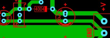
The regulator output negative point is typically best made at an output bypass filter cap (eg. the 10uF filter cap). The aim is then to connect the amplifier load also to that output bypass filter cap negative terminal (for 317 circuit). If that bypass cap was ideal then load current would only flow in to and out of that cap, and similarly power supply current would also only flow in to and out of that cap. The post #67 layout generally does that appropriately.
My earlier comment on connecting the reg adj circuit 'out the back' of the 317 pads was to make the 317 output pad a kelvin connection point. As such, the 240 ohm resistor would connect to the 4004 trace on the other side of the 317, rather than connect to the trace going to the output cap and load.
Last edited:
ammel, Figure 3 in the LT LM317 datasheet should make this clearer.
Yes it does. Thanks for the link.
From what I interpret in fig. 3, the ground from the trimmer should connect to the center plane as close to the load(or terminal block in this case?) as possible.
Someone in an earlier post suggested moving the 10uF caps close to the heatsinks.
If the trimmer's ground connects to the output caps' ground pad, moving the caps back toward the heatsinks seems counterintuitive to what the L.T. datasheet suggests.
So where is the best location for the 10uF caps?
Yes, the -sense should go to the load or as close to the load a possible.Is it any better to connect the -sense point and output cap's gnd. to the terminal block's ground like shown below?
That usually means the regulator should be placed at the load.
I would suggest that a pedantically correct layout would make the output cap negative pad the star point for connecting to the rectifier filter supply input, the load output, and the relavent regulator sensing.
The compromise is that you have one 0V terminal for load connection.
The compromise is that you have one 0V terminal for load connection.
True, but it's worthwhile appreciating what is at the best end of the scale, and what is practically done, and why there is likely no difference for your application.
For example, a designer could want seperate PT winding, rectifier, filter, regulator for each supply rail for each amp section. Practical decisions are made normally, sometimes by bean counters in a company, sometimes by the designer appreciating that any benefit is negligible for that application.
For example, a designer could want seperate PT winding, rectifier, filter, regulator for each supply rail for each amp section. Practical decisions are made normally, sometimes by bean counters in a company, sometimes by the designer appreciating that any benefit is negligible for that application.
Trobbins, you're right. Just another example of "potentially there's always room for improvement" with almost anything.
Thank you and the others here for their contribution fine tuning my layout.
Think I'm going to get some Gerbers off to one of the Chinese board houses when they're done celebrating their Chinese New Year.
Thank you and the others here for their contribution fine tuning my layout.
Think I'm going to get some Gerbers off to one of the Chinese board houses when they're done celebrating their Chinese New Year.
Depending on your board size I'd recommend Itead's pcb prototyping service. I used them for my active crossover board and got 10 boards for under $30 US including shipping! Way cheaper than even the setup costs for a lot of places. https://www.itead.cc/open-pcb/pcb-prototyping.html
Tony.
Tony.
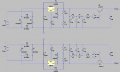
C3 and C9 should not be low-ESR polymers for proper LM317 stability.
As for the others..... well, this schematic is a bit weird. Why stick a capacitance multiplier at the output of a LM317?... The output impedance of this thing is going to be huuuuuuuge...
As for the others..... well, this schematic is a bit weird. Why stick a capacitance multiplier at the output of a LM317?... The output impedance of this thing is going to be huuuuuuuge...
I found the circuit over in one of the headphone forums. The F5 headphone amp thread I believe.
Rumor was it's a circuit John Curl design and used in a Parasound product. I asked him about it and he stated he had never seen the circuit before.
So output impedance is going to be too high?
Rumor was it's a circuit John Curl design and used in a Parasound product. I asked him about it and he stated he had never seen the circuit before.
So output impedance is going to be too high?
At very low frequencies approximately 2 kT/(q Iout) + 2100 ohm/(hfe1 hfe2) ~= 52 mV/Iout + 2100 ohm/(hfe1 hfe2) for each output rail. At higher frequencies, first the 2100 ohm/(hfe1 hfe2) term disappears and then the output capacitors kick in.
Whether this is too high or perfectly acceptable depends on the application.
I guess the circuit is meant to filter off the noise of the LM317/LM337. Depending on load current, it could help to add extra resistors to bias the BC550C and BC560C at more predictable currents.
Whether this is too high or perfectly acceptable depends on the application.
I guess the circuit is meant to filter off the noise of the LM317/LM337. Depending on load current, it could help to add extra resistors to bias the BC550C and BC560C at more predictable currents.
If the capacitance multiplier was placed before the regulator, it could boost its ripple rejection. However, placing it after the regulator will just add loads of nonlinear output impedance...
- Status
- Not open for further replies.
- Home
- Amplifiers
- Power Supplies
- LM317/337 Schematic Questions.