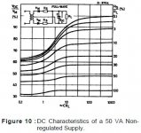
I'm not talking about inrush. The total power transferred has to be put into the reservoir caps during the time the diodes conduct, which typically is between 20% to 10% of the mains period. If you have a large cap, the voltage droop is smaller and the conduction angle for the diodes gets shorter. The shorter the conduction angle, the higher the peak current to transfer the required power.
For a very rough approximation, if the DC load is 1A, and the conduction of the diodes is 10% of the period, necessarily the diode peak current will be > 10A.
Jan
No, I don't think so. The peak current is determined by circuit resistance, mostly transformer winding resistance, and secondary voltage. Other contributors to the resistance are mains resistance, filter capacitor ESR, wiring and connector resistances. Please visit the link I posted to see some tables of peak current vs. capacitance for linear power supplies.
Jan is correct to say that 1A out and 10% duty cycle in means peaks of 10A.
Bill is correct to say that the duty cycle does not keep reducing as cap value increases, but gets limited by circuit impedance.
So you are both right.
Bill is correct to say that the duty cycle does not keep reducing as cap value increases, but gets limited by circuit impedance.
So you are both right.
Yes Bill is right. The duty cycle gets limited by the upstream impedances, so at a certain point when increasing the reservoir caps, the duty cycle is not decreasing but the output voltage will start to drop.
So that makes three of us sort of agreeing. I think that is a first here. Finally, after 10+ years! ;-)
Jan
So that makes three of us sort of agreeing. I think that is a first here. Finally, after 10+ years! ;-)
Jan

at a certain point when increasing the reservoir caps, the duty cycle is not decreasing but the output voltage will start to drop.
The DC output voltage should be substantially unchanged as filter capacitance increases. The output ripple voltage decreases as capacitance rises. Rod Elliot says the DC output rises ever so slightly as capacitance increases.
The DC output voltage should be substantially unchanged as filter capacitance increases. The output ripple voltage decreases as capacitance rises. Rod Elliot says the DC output rises ever so slightly as capacitance increases.
OK, this is my reasoning, tell me what you think:
If you increase output cap, the current pulses tend to shorten and get higher (to keep up with the power demand) until you get to the point where the transformer and rectifier impedances start to come into play.
So the current pulses cannot get appreciably higher, but if your demand still rises, the only way to transfer more power is by widening the current pulses at the max height. That means that the diodes start to conduct at a lower voltage, but cannot (because of the impedances) load up the caps to the theoretical secondary voltage. As a result the average output voltage drops.
I have seen this many times: the rising voltage on the cap will still be lower than the secondary peak voltage when the sine wave already is dropping again after the peak value and the diodes block, so the caps never get charged up to the peak voltage.
Jan
I find that hard to believe. Are you distinguishing between average output voltage and peak output voltage? I can believe that the peak might fall with a big cap because it doesn't have time to fully charge up, but the average should still increase by a little.
My comments assume a fixed load current. Increasing capacitance does reduce output ripple voltage which has the effect of increasing the average output voltage slightly.
For normal values of filter capacitance, say 4700uF to 100000uF, diode conduction time and diode current peaks vary very little over the whole range of capacitance. Very small filter capacitors allow large output ripple and are not typically used in practice, especially in diy audio projects where overkill capacitance is often employed.
Keep in mind that Ohm's Law and conservation of energy must be satisfied in any valid explanation of circuit action.
My comments assume a fixed load current. Increasing capacitance does reduce output ripple voltage which has the effect of increasing the average output voltage slightly.
For normal values of filter capacitance, say 4700uF to 100000uF, diode conduction time and diode current peaks vary very little over the whole range of capacitance. Very small filter capacitors allow large output ripple and are not typically used in practice, especially in diy audio projects where overkill capacitance is often employed.
Keep in mind that Ohm's Law and conservation of energy must be satisfied in any valid explanation of circuit action.
OK, I think you guys are right, there''s no droop. I did some sims and they agreed with you not with me.
Maybe I need a new sim 😎
Jan
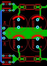
Panasonic caps and diode connections.
Are these Panasonic 10uF electros okay for using with LM regs.?
I don't see low ESR mentioned anywhere in their datasheet.
http://www.mouser.com/Search/Produc...0Ivirtualkey66720000virtualkey667-ECA-2AM100I
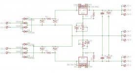
Also can someone please verify if my diode connections below are correct?
I always seem to get confused as to their orientation.😱
Thanks!
Are these Panasonic 10uF electros okay for using with LM regs.?
I don't see low ESR mentioned anywhere in their datasheet.
http://www.mouser.com/Search/Produc...0Ivirtualkey66720000virtualkey667-ECA-2AM100I
Also can someone please verify if my diode connections below are correct?
I always seem to get confused as to their orientation.😱
Thanks!
Attachments
When it doesn't say 'low ESR' or put the ESR numbers in the table, its fairly safe to assume they're not low ESR.
Here is one I came up with last year.
Feel free to reverse engineer it.
Feel free to reverse engineer it.
Attachments

Last edited:
Feel free to reverse engineer it.
I find 8 diodes in your circuit vs. 4 diodes in my circuit confusing to reverse engineer.
Thanks anyway.
Yes, a full wave bridge for each rail.
It will make for a smoother DC that the LM317/337 will need to regulate.
It will make for a smoother DC that the LM317/337 will need to regulate.
According to this, C5 and C6 look like pretty good ideas to have:
http://www.tnt-audio.com/clinica/regulators_noise2_e.html
http://www.tnt-audio.com/clinica/regulators_noise2_e.html
Hmm...that shows replacing the 10uF caps with much larger 220uF caps.
Others say 220uF is too much. Seems there's no consensus here on what value to use.
Others say 220uF is too much. Seems there's no consensus here on what value to use.
That might be because a lot of different manufacturers made 317 type regulators and no doubt they were different from each other inside.
- Status
- Not open for further replies.
- Home
- Amplifiers
- Power Supplies
- LM317/337 Schematic Questions.