Hi!
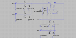
Based on Esa Meriläinen’s project Transconductance amplifier project | Current-Drive - The Natural Way of Loudspeaker Operation I built similar easy transconductance amp on LM1875s.
V1,2 are just the working supply voltages from Philips F4220 dead amp.
For the simplicity on the schematic bellow there is no right channel which is identical as left.
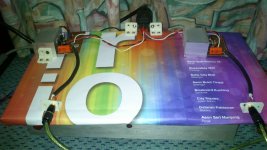
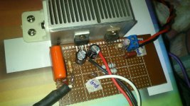
The chips and mosfets are mounted on original heatsink from the amp.
I used volume pot, input circuitry, output sockets from the amp too.
The sound is absolutely fantastic, reminds good sounding tube amps, especially in detailed and silk trebles and mids but without heat losses and massive transformers. I made several tube SE and PP amps before and I know what I am writing.
As transconductance amp, it has very high output impedance, some speakers might sound boomy due to not existing damping factor. I tried it with Jamo Compact 90, Saba Acoustic Monitor 80, Sansui SP3000A with excellent results.
Please read carfully Joe’s excellent thread to prevent any damages.
The project is simply but is worth the best parts like caps, resistors, power supply, etc. due to extraordinary sound.
Power indicators from Philips F4220 at party volume levels are showing only ~5W😀
Have fun!
Based on Esa Meriläinen’s project Transconductance amplifier project | Current-Drive - The Natural Way of Loudspeaker Operation I built similar easy transconductance amp on LM1875s.
V1,2 are just the working supply voltages from Philips F4220 dead amp.
For the simplicity on the schematic bellow there is no right channel which is identical as left.
The chips and mosfets are mounted on original heatsink from the amp.
I used volume pot, input circuitry, output sockets from the amp too.
The sound is absolutely fantastic, reminds good sounding tube amps, especially in detailed and silk trebles and mids but without heat losses and massive transformers. I made several tube SE and PP amps before and I know what I am writing.
As transconductance amp, it has very high output impedance, some speakers might sound boomy due to not existing damping factor. I tried it with Jamo Compact 90, Saba Acoustic Monitor 80, Sansui SP3000A with excellent results.
Please read carfully Joe’s excellent thread to prevent any damages.
The project is simply but is worth the best parts like caps, resistors, power supply, etc. due to extraordinary sound.
Power indicators from Philips F4220 at party volume levels are showing only ~5W😀
Have fun!
Attachments
Nice and simple circuit to verify the concept.
Kindly share your views (even if it will be subjective) on the following:
1. Lo, mid and hi while listening to music
2. Dialogues, music and effects while listening to movies
This will help me/ us visualize where a current drive makes a difference.
Also, are you planning to use this with a full range in a sealed enclosures?
Thanks!!
1. Lo, mid and hi while listening to music
I would say, the highest quality low, mid and hi with the remark that the resonant frequency of the speakers might be boosted
2. Dialogues, music and effects while listening to movies
I did not check, but I started to think about rebuilding sound amps in my TV and 2.1 Creative pc amp to current drive...
Also, are you planning to use this with a full range in a sealed enclosures?
the names of the speakers from the first post are fully enclosured full range speakers
Thank-you for your quick reply.
Kindly do find some time to check it out with TV and post an update here.
Thanks again!
This is going to be inspirational!!
Kindly do find some time to check it out with TV and post an update here.
Thanks again!
This is going to be inspirational!!
Hello Pawel,
Thanks for sharing. I will build this soon. few questions
1) You used the IRF 9540 as cap multiplier ? Or to drop the V ?
2) What size transformer ?
3) What is the expected power output with 24 V power supply ?
4) What is the pre amp used?
5) What is the function of 5.4 and 68 resistor ?
6) Can i used +/- 24 V dc power supply ?
7) Is the input cap in the signal necessary ? Can this be substituted for 10 UF ?
My speaker is 7 R Markaudio 12 P
Thanks
kp93300
Last edited:
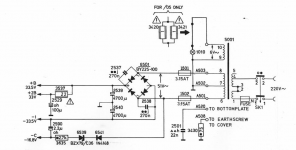
zener type regulator but you can use LM7824/7924 or use no stabilisation if the voltage of power supply will be lower than +/- 30V1) You used the IRF 9540 as cap multiplier ? Or to drop the V ?
attached picture of the schematic of power supply of Philips F4200 inside which I built amp. As you can see the transformer is not too big, with ct 50Vac which gives +/- 33VDC after rectifying and filtration and this was one of the reasons I decieded to use zener type regulators with IRFs2) What size transformer ?
single or double? circa 20W @+/- 24VDC3) What is the expected power output with 24 V power supply ?
no preamp, just volume pot from F42204) What is the pre amp used?
5.4 is speaker resistance (measured), 68 is for protection when no load at the amp5) What is the function of 5.4 and 68 resistor ?
max for 1875 is +/-30VDC, so yes!6) Can i used +/- 24 V dc power supply ?
in general yes, necessary, and you can use 10uF7) Is the input cap in the signal necessary ? Can this be substituted for 10 UF ?
there should be not the problem with driving them.My speaker is 7 R Markaudio 12 P
BTW loading input resistor with the value of 22k gived the lowest offset at the output (a few mV)
Attachments
current drive based on TDA7293
Hello again,
I finally built a current drive based on TDA7293. Big amp really for my needs...
A non-inverting configuration with DC blocking RC input filter and the loudspeaker with the sense resistor forming the gain components. No R-C across the output.
I added a DC servo loop to keep the output DC in check.
I tested it with as many full-range loudspeakers, in sealed enclosures, that I had.
The results are simply fantastic. Each one of them sounded as if it was 4 times as big and 4 times as expensive.
I confidently shorted the output much to the amusement of the watchers.
Bass, Mid-range and treble associated with dialogues, music and effects, whether listening to music tracks or watching a movie all get placed correctly.
It seems like a per-equalized system.
Without the current drive, the same content becomes unbearable, dull and lifeless, so beware.
All audio DIYers must do this at least once.


I intend to build the circuit in the first post.
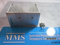
Is this heatsink big enough?
Power supply is+/_ 24 v dc.
speaker is markaudio 12P.
Can i expect about 20 W from this amp ?
thks
kp93300
Heatsink - I do not know, I guess so
power s is OK
speaker resistance is?
slightly less than 20W, I would say 18W, but this is plenty
so you can use 2*1 Ohm 1W resistors in parallel (=0.5 Ohm) instead of 3 (=0.33 Ohm) for current sensing
Thanks to Pawel.
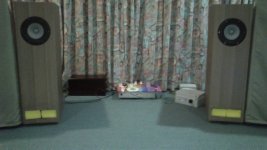
This is my build of the amp.
There is too much bass with the markaudio 12p in superpensil. The bass notes are not well controlled.
I change the input cap from 10 uf to 0.7 uf and still too much bass.
i close off the outlet of the speaker with foam and is much better.
Otherwise, mid , high and soundstage are all very good.
Vocal is the best i have heard in my set up.
Piano and guitar are very nice and natural .
The high frequency is very refined like tubes.
Is there any other adjustment to tighten the bass ??
thanks
kp93300
Attachments
Hello again,
I finally built a current drive based on TDA7293. Big amp really for my needs...
A non-inverting configuration with DC blocking RC input filter and the loudspeaker with the sense resistor forming the gain components. No R-C across the output.
I added a DC servo loop to keep the output DC in check.
I tested it with as many full-range loudspeakers, in sealed enclosures, that I had.
The results are simply fantastic. Each one of them sounded as if it was 4 times as big and 4 times as expensive.
I confidently shorted the output much to the amusement of the watchers.
Bass, Mid-range and treble associated with dialogues, music and effects, whether listening to music tracks or watching a movie all get placed correctly.
It seems like a per-equalized system.
Without the current drive, the same content becomes unbearable, dull and lifeless, so beware.
All audio DIYers must do this at least once.
can you share your schematic ?
thanks thiagomogi for the suggestions .
What about raising the value of the resistor from speaker negative to ground? I have 0.5 R now.
What about raising the value of the resistor from speaker negative to ground? I have 0.5 R now.
superb!
I wrote about this, this amp has very high output impedance, so resonances in the speaker are not damped.
you can build active eq knowing parameters of your speakers: section Bass equalization Transconductance amplifier project | Current-Drive - The Natural Way of Loudspeaker Operation
The bass notes are not well controlled.
Is there any other adjustment to tighten the bass ??
thanks
kp93300
I wrote about this, this amp has very high output impedance, so resonances in the speaker are not damped.
you can build active eq knowing parameters of your speakers: section Bass equalization Transconductance amplifier project | Current-Drive - The Natural Way of Loudspeaker Operation
thanks thiagomogi for the suggestions .
What about raising the value of the resistor from speaker negative to ground? I have 0.5 R now.
because your speakers are 7.2 Ohm dc resistance you can put for example 0.68 Ohm resistor but not higher, 1875s are not so stable...
This will create more nfb factor, less distored sound but not cause more controll on bass resonance.
I think in your case mechanical damping of speakers enclosure is the best way to damp bass resonance frequency.
Hi Pawel,
I want to buid this amp too. For a Visaton BG20 in open baffle, Rdc=6.3 ohm, should i change something in your schematic? I plan to use +- 24V Dc power supply.
The sistem is 3 way active, so this speaker will be crossed 120hz LR4 HighPass.
Thank you!
I want to buid this amp too. For a Visaton BG20 in open baffle, Rdc=6.3 ohm, should i change something in your schematic? I plan to use +- 24V Dc power supply.
The sistem is 3 way active, so this speaker will be crossed 120hz LR4 HighPass.
Thank you!
should i change something in your schematic?
no, it should work as it is!
but please read about the safety: http://www.diyaudio.com/forums/chip...-watt-transconductance-current-amplifier.html
- Status
- Not open for further replies.
- Home
- Amplifiers
- Chip Amps
- LM1875 transconductance amp