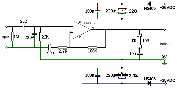
@AndrewT, this is the case: Putting more power IN is wishful thinking, because the internal transistors are so very tiny. Although the speaker output pin is short protected, overcurrent provided INTO Any pin can decrease longevity to a period of months instead of the expected years of service. Anyway, the thread is titled "LM1875 Power Supply+Transformer Considerations" which is where if you didn't spend too much, then you can get bonus overcurrent protection.
When those conditions are all met (including a limiting factor Other than LM1875), it can drive heavy load speakers quite easily.
If split rail power is used, the gain divider doesn't have to be so light current as the single rail example, but rather THIS (schema) has been driving 4 ohm speakers just fine for years (these are monoblocs with 36va transformers, and separate power board with 2x2200u per rail).

That one is nicknamed "LM1875 Turbo II" which literally means version 2 of a gain comp'd chip amp. The previous version has slightly higher gain, only one 220u per rail and didn't have the 1N5405 (no other differences). The power circuit changes in this "II" were made for better quality imaging. Both use a separate power supply board (not shown) and little 36va transformers (for longevity, of course).
Notes:
The 10n is a placeholder, but the value can and should be increased (different layout takes different values).
The 22k can be changed for tonal needs, range 15k~75k, and one could use lighter, such as 27k for more placid tone or heavier, such as 15k for more authority; therefore, instead of the 22k, it will be fun to install a 50k multi-turn variable resistor and just dial it in to suit personal taste.
The 100u can be used along with adding a little polyester bypass cap, such as 4n7 or a little more.
The amp is more durable and longer lasting when the power input current can't exceed the output current (for heatsink + speaker), when it is fully ac coupled, and when the gain divider is light current as in the datasheet's single rail example.I don't understand the P.P.P.S. explanation. The inputs can withstand rail voltage levels. The input current is less than 2 uA.
When those conditions are all met (including a limiting factor Other than LM1875), it can drive heavy load speakers quite easily.
If split rail power is used, the gain divider doesn't have to be so light current as the single rail example, but rather THIS (schema) has been driving 4 ohm speakers just fine for years (these are monoblocs with 36va transformers, and separate power board with 2x2200u per rail).

That one is nicknamed "LM1875 Turbo II" which literally means version 2 of a gain comp'd chip amp. The previous version has slightly higher gain, only one 220u per rail and didn't have the 1N5405 (no other differences). The power circuit changes in this "II" were made for better quality imaging. Both use a separate power supply board (not shown) and little 36va transformers (for longevity, of course).
Notes:
The 10n is a placeholder, but the value can and should be increased (different layout takes different values).
The 22k can be changed for tonal needs, range 15k~75k, and one could use lighter, such as 27k for more placid tone or heavier, such as 15k for more authority; therefore, instead of the 22k, it will be fun to install a 50k multi-turn variable resistor and just dial it in to suit personal taste.
The 100u can be used along with adding a little polyester bypass cap, such as 4n7 or a little more.
Last edited:
One does NOT put more power in.
One supplies adequate voltage and the amplifier DEMANDS the current it needs to pass on to the amplifier load.
One supplies adequate voltage and the amplifier DEMANDS the current it needs to pass on to the amplifier load.
Speaking of amplifier load. . .
The 14-0-14vac or 15-0-15vac center tap transformers can be used. Allied Electronics has them store-branded. Old style 13.5-0-13.5 heater transformers can be used and those are very low cost.
The schematic at post#41 would need the 100k at a lower figure (for lower gain) so as to adapt it to the lower voltage use; so, instead of 100k, 75k would be worth a test drive.
P.S.
To save a bit on shipping, perhaps the TO220 size mica insulators and Shoulder Washers and possibly even heatsinks too, may ride along with the transformers (sometimes all in one box cost less on shipping).
So, applying that:Around 6 Ohms
The 14-0-14vac or 15-0-15vac center tap transformers can be used. Allied Electronics has them store-branded. Old style 13.5-0-13.5 heater transformers can be used and those are very low cost.
The schematic at post#41 would need the 100k at a lower figure (for lower gain) so as to adapt it to the lower voltage use; so, instead of 100k, 75k would be worth a test drive.
P.S.
To save a bit on shipping, perhaps the TO220 size mica insulators and Shoulder Washers and possibly even heatsinks too, may ride along with the transformers (sometimes all in one box cost less on shipping).
The chip can also be used at lower power, much more simply, like this:
Gobo Stereo Audio Amplifier Kit (LM1875, 15W, Class-AB) - Review
https://www.boxedkitamps.com/gobo-stereo-audio-amp-kit
Check out the bamboo! 🙂
This is using an ordinary little 12-0-12vac transformer, which is not expensive, the low voltage has apparently made the datasheet sample schema work appropriately, and the low heat has made the build much simpler.
- Status
- Not open for further replies.