
Khron said:1) Change the location of the 1M with the 10ohm
2) You seemed to like my layout 🙂 It's a bit more compact as well.
Ah, heatsink fits fine.
I think its nicest when the back of the chip is flush/even with the edge of the board.
Maybe you can unblock the V+ connection (like move zobel cap to right side of board)?
Looks good to me. I would use a 220uf for the blocking cap and put a .1uf film cap parallel. You have the room, why not.
Cool guys!
Howabout a stereo board next?
Advantages of a stereo board:
There is only 2 of 220uF caps for power.
Expected results on project completion.
Safer--The chip won't spin to slip off the insulator.
LM1875 is interesting parallel and TDA2050 is interesting bridged.
More-easily scalable for wide variety of applications.
Physically more durable.
Lower costs.
Simplified wiring.
And, given a pair of stereo boards, one can be used in parallel mode to power a 4 ohm subwoofer, while the other is used normally, as for the main speakers. This can run from just one transformer if that is your budget or preference.
Perhaps one owns 4 ohm MTM, 4to8, "difficult drive," planar, or other speaker types (use parallel)?
Perhaps one owns full range drivers at the end of very long speaker cables or regular 16 ohm speakers (use bridged)?
I think that a stereo board brings with it some economy and ease in studying the various applications of chip amps.
Now that you have combined the two channels at that Central Star, how do you make a decision on where the PSU zero volt line should be referenced?Khron said:Would something like this be satisfactory?
And, possibly more importantly, where do you take the speaker return wire to?
finish layout of lm 1875, maybe? 😀
please comment, if everything is good i will make this revision pcb next day to replace my old pcb, thx
An externally hosted image should be here but it was not working when we last tested it.
please comment, if everything is good i will make this revision pcb next day to replace my old pcb, thx
I like the alternative pin pitch pads for the two caps.
What about a similar philosophy for the six other caps?
bring the two input pads to 0.1inch pin pitch.
bring the input end of the 22k Zin to outside these two input pins, but on the hot input side.
This gives a three pin input @ 0.1inch pitch. A computer type jumper plug (0.1inch pitch) can be used to short either pin to it's neighbour.
It also allows you to bypass the input DC block if you have DC blocking at the previous stage. Finally it allows you to short the AC input to signal ground for testing and setting up.
Khron said:Would something like this be satisfactory? 🙂
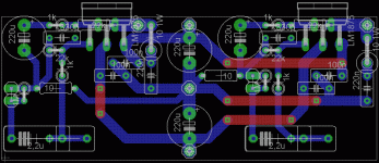
That stereo board has the right side with the power cap too close to the nfb cap and, one of the power leads crosses, via jumper, straight over the signal. The left and right won't sound identical, thus it couldn't be used parallel unless output resistors were increased quite a bit.
Other than that, its looking good.
Suggestion: Use no jumpers. The resistors can reach.
AndrewT said:Now that you have combined the two channels at that Central Star, how do you make a decision on where the PSU zero volt line should be referenced?
And, possibly more importantly, where do you take the speaker return wire to?
Doesn't the PSU 0v connect right in the center of that stereo board?
Doesn't the speaker return connect to the 0v output terminal of the power supply board?
try it and report your results.danielwritesbac said:the PSU 0v connect right in the center of that stereo board.
The speaker return connect to the 0v output terminal of the power supply board?
AndrewT said:try it and report your results.
Bit of "sink the mids" arrangement. Mine is operated parallel. I'm not sure about only using 2 of 220uF caps, except that stereo chips use only two caps. Are there additional components required for this?
btw where is the signal resistor.... i wanna replace with MF resistor like riken/rodenstein?
thc
thc
there are six small resistors on the PCB only the 10r connecting signal ground to power ground does not pass signal.
sneih said:btw where is the signal resistor.... i wanna replace with MF resistor like riken/rodenstein?
thc
All of the pins of an op amp are a potential input.
Every part of a running amplifier has a signal, with the point being, to give it a direction.
Metal film is great at all-band rejection. So, it could be good for negative feedback.
Negative feedback (NFB): Everything is amplified with infinite gain--except for what you tell it not to do.
Confining your amplifier to the audio band will make it more powerful during the audio band, in that greater efficiency does have that outcome.
Therefore use metal film for feedback and input impedance. In the recent designs posted, those two resistors are 22k.
http://www.diyaudio.com/forums/attachment.php?s=&postid=1508773&stamp=1210693455 Click the link and see the picture by Peter Daniel, Audiosector, demonstrating that resistors against audio signal are metal film, but where greater isolation is needed, a carbon resistor is employed.
AndrewT said:
bring the two input pads to 0.1inch pin pitch.
bring the input end of the 22k Zin to outside these two input pins, but on the hot input side.
This gives a three pin input @ 0.1inch pitch. A computer type jumper plug (0.1inch pitch) can be used to short either pin to it's neighbour.
It also allows you to bypass the input DC block if you have DC blocking at the previous stage. Finally it allows you to short the AC input to signal ground for testing and setting up.
btw i m noob!!
that idea is hard to me to do!
maybe someone can realize that..
danielwritesbac said:
All of the pins of an op amp are a potential input.
Every part of a running amplifier has a signal, with the point being, to give it a direction.
Metal film is great at all-band rejection. So, it could be good for negative feedback.
Negative feedback (NFB): Everything is amplified with infinite gain--except for what you tell it not to do.
Confining your amplifier to the audio band will make it more powerful during the audio band, in that greater efficiency does have that outcome.
Therefore use metal film for feedback and input impedance. In the recent designs posted, those two resistors are 22k.
http://www.diyaudio.com/forums/attachment.php?s=&postid=1508773&stamp=1210693455 Click the link and see the picture by Peter Daniel, Audiosector, demonstrating that resistors against audio signal are metal film, but where greater isolation is needed, a carbon resistor is employed.
thx daniel, i have learns so much from you n others!!
sneih said:thx daniel, i have learns so much from you n others!!
I think that I learn something every day. To me, there is some fun in getting to try them out and listen to what things do.

- Status
- Not open for further replies.
- Home
- Amplifiers
- Chip Amps
- LM1875 PCB, Which To Use