mosfets said:
Can the input components be modified so only low freq Hz will pass ie 150Hz and below? You know, to drive a little subwoofer!😎 This looks very neat BTW!
The techniques of tone controls with op amps do also work on really big op amps. Check out the circuit of a bass booster, and that will give you ideas--its quite a similar approach to amplify bass as it is to amplify only bass. 😉
mosfets said:Furthermore, can this preamp be used to drive three of these LM1875 PCBs?
It is meant to drive a stereo pair.
If you are using a 3 channel amplifier for computer, then you will want either a 3 channel preamp or no preamp.
LM1875 kit from Nimo e-store on e-bay
Hi,
I just bought this kit on e-bay, I hope if sounds good. Seller can provide only the PCB but I'm not sure if the design is good.
http://cgi.ebay.com/Power-Amplifier...photoQQcmdZViewItemQQ_trksidZp1742.m153.l1262
Regards,
Eric
Hi,
I just bought this kit on e-bay, I hope if sounds good. Seller can provide only the PCB but I'm not sure if the design is good.
http://cgi.ebay.com/Power-Amplifier...photoQQcmdZViewItemQQ_trksidZp1742.m153.l1262
Regards,
Eric
Look this
I think it is better than you ever look.
http://bbs.hifidiy.net/viewthread.php?tid=153104&highlight=1875
and then, learn some Chinese 🙂
hehe
I think it is better than you ever look.
http://bbs.hifidiy.net/viewthread.php?tid=153104&highlight=1875
and then, learn some Chinese 🙂
hehe
Hi Qxxy19,
Based on what you can understand from your link is it a good design or not, I did not learn chinese yet 🙂
Thanks,
Eric
Based on what you can understand from your link is it a good design or not, I did not learn chinese yet 🙂
Thanks,
Eric
i have also bought this chinese lm1875 kit.
any comments on the pcb design?
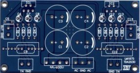
also i want to note that my kit came with 4 fake rubycon yxa series 4700uf 35v caps.
c1, c2, c3, c4 - 4700uf 35v
c5, c14 - 0.1uf
c6, c7, c8, c11, c12, c13 - 22uf
c9, c10 - 1uf
r1 , r9 - 1r
r2, r6 - 680r
r3 - 22k
r4, r5, r7, r8 - 22k
any comments on the pcb design?
also i want to note that my kit came with 4 fake rubycon yxa series 4700uf 35v caps.
c1, c2, c3, c4 - 4700uf 35v
c5, c14 - 0.1uf
c6, c7, c8, c11, c12, c13 - 22uf
c9, c10 - 1uf
r1 , r9 - 1r
r2, r6 - 680r
r3 - 22k
r4, r5, r7, r8 - 22k
Attachments
davidgale said:i have also bought this chinese lm1875 kit.
any comments on the pcb design?
also i want to note that my kit came with 4 fake rubycon yxa series 4700uf 35v caps.
c1, c2, c3, c4 - 4700uf 35v
c5, c14 - 0.1uf
c6, c7, c8, c11, c12, c13 - 22uf
c9, c10 - 1uf
r1 , r9 - 1r
r2, r6 - 680r
r3 - 22k
r4, r5, r7, r8 - 22k
I, for one, would like some explanation of R5, 22k from the speaker output of one amp to the inverting input of the other amp. Half of a crossfade circuit? What the heck?
davidgale said:i have also bought this chinese lm1875 kit.
any comments on the pcb design?
also i want to note that my kit came with 4 fake rubycon yxa series 4700uf 35v caps.
c1, c2, c3, c4 - 4700uf 35v
c5, c14 - 0.1uf
c6, c7, c8, c11, c12, c13 - 22uf
c9, c10 - 1uf
r1 , r9 - 1r
r2, r6 - 680r
r3 - 22k
r4, r5, r7, r8 - 22k
One more interesting item in this design is the NFB cap, 22uF.
This design drives the cap directly rather than through the resistor.
And then both the cap and resistor can operate normally, because this orientation has less reliance on component quality/variance, given the 680R higher efficiency into the cap, if compared with the LM1875.PDF design.
I'm trying to say that the design you've pictured has the 680R operating as a simple resistor like it should, and the attached cap NOT operating like a really bad cap.. 😉
Its the only AC coupled NFB, chipamp design that I've ever seen to address this little issue.
Whether the design works great or not, they surely deserve some Kudos! just for getting creative. 😀
I'd love to know what you think of it.
Hi,
I just received from the e-bay seller an assembly drawing (it does not come with a schematic) and R5 which is 22k is for BTL configuration. For normal stereo R5 must be omited.
Regards,
Eric
I just received from the e-bay seller an assembly drawing (it does not come with a schematic) and R5 which is 22k is for BTL configuration. For normal stereo R5 must be omited.
Regards,
Eric
AndrewT said:Hi Daniel,
which schematic are you referring to?
OH hi Andrew! 😉
Its "Typical Applications" on page 1 of LM1875.pdf and I'm referring to "C2." Other NatSemi chip amps and the Overture spreadsheet refer to it as "CI."
And why. . .
National semiconductor prefers to have the resistor on the chip pin and then drive the cap from the opposite side of the resistor, thus simulating a cap with extremely high ESR; however, the chinese board has the cap driven directly. That's different.
Khron said:I've put together a (small) pcb for LM1875
Did you actually build one like this? There seem to be quite a bunch of overlapping components. Three of the electrolytic capacitors are not entirely on the PCB, which is not good for the mechanical stability.
Why are you using an electrolytic capacitor in parallel to the MKP(?) blocking capacitor?
No, i haven't built one precisely like this, but i have a pair of LM1875 amps back home with quite small pcb's (in working order, last time i checked).
The overlapping components issue shouldn't be that severe. I used a 7mm diameter 'lytic for that feedback cap in the middle, but a 47u/16V cap usually isn't much bigger than 5-6mm. A quick package change can take that all away 🙂
Regarding mechanical stability... I'm guessing these amps won't be mounted on board jackhammers, for the workers' enjoyment, and 10mm diameter caps don't weigh more than a few (tens of?) grams, so that might not be a crucial problem either.
Yeah, that's a 'lytic on the input. For less pretentious users and/or convenience, i suppose. The small film cap should take the "sting" out of the non-film
Nordic said:
I measuered the fuses, they are not worth wile takeing out I think, you gain a handful of mm at best.
I tried a few layout, each have their own issues, like mounting holes etc...
This one seems to be the best, good routing, can accommodate a number of diffirent caps by drilling hole in inline trace... and on input cap you can choose between two points for connecting one of the leads, by cutting through the other trace with a blade.
An externally hosted image should be here but it was not working when we last tested it.
i has finally make this pcb yesterday (home made) but i wondering one thing!!
i find mistake of capacitor polarity (220uF/35V) at nordic layout
it's right? cmiiw?
^
thx for this information!!
btw that is my first homemade 1875 pcb:
-------------------------------------------------------------------------------------
finally this is pcb layout based nordic layout (some modiy for fit with 2,2uf caps)
thanks so much to nordic!!
thx for this information!!
btw that is my first homemade 1875 pcb:
An externally hosted image should be here but it was not working when we last tested it.
-------------------------------------------------------------------------------------
finally this is pcb layout based nordic layout (some modiy for fit with 2,2uf caps)
An externally hosted image should be here but it was not working when we last tested it.
An externally hosted image should be here but it was not working when we last tested it.
thanks so much to nordic!!
Originally posted by Greg Erskine
quote:
Originally posted by danielwritesbac
Center pin of LM1875 is -v
OMG! I just got quoted by a guru. I'm smiling like the cheshire cat. 😀
Wow. Thanks man!
P.S. It seems that the computer software that Nordic used, had partially obscured the polarity markings for V+ and V- power inlet terminals, which is what led to the error. This could have happened to anyone if using that software. This reminds me. I need to go buy a new automatic pencil. 😉
- Status
- Not open for further replies.
- Home
- Amplifiers
- Chip Amps
- LM1875 PCB, Which To Use