Hi there, I finally got my amplifier all put together and everything ready to go using the parallel config (audio sector kit with r0 omitted, inputs sharing r4). I checked the DC offset with no load or input connected and got 182 mv on the right channel and 162 mv on the left. I then connected a source (focusrite ls56 interface) a rechecked, since the offset should go down due to low impedance of the input. Still very high, 143mv and 110mv.
Can anyone offer advice or an explain it like I'm 5 diagnosis of this? From everything I have read, the DC offset should be under 50mv
Can anyone offer advice or an explain it like I'm 5 diagnosis of this? From everything I have read, the DC offset should be under 50mv
The worst case offset for the chip itself is 10 mV. However, if you have an amp with gain at DC, you'll see (Gain)*(Offset) on the output of your amp. So if you have a gain of 20x (= 26 dB), you can see up to 200 mV of offset on the output.
There are a couple of ways to address this:
* Capacitor to ground in the feedback path to lower the DC gain to 1x (0 dB).
* Use a DC servo.
* Use DC offset trim.
In your case, it sounds like a cap to ground is the winner. There's probably a spot on the board for it.
Tom
There are a couple of ways to address this:
* Capacitor to ground in the feedback path to lower the DC gain to 1x (0 dB).
* Use a DC servo.
* Use DC offset trim.
In your case, it sounds like a cap to ground is the winner. There's probably a spot on the board for it.
Tom
There's no spot on the board for a feedback cap to ground on those boards.
I get <2mV on mine using stock values. I changed out the four signal path devices to surface mount resistors though, the 1206 size just about touches the pads.
I would check again, and very thoroughly. That level of offset seems extremely high. Can you show how you have wired up the power supply?
And some pictures are always helpful. Cameras can pick up stuff your eyes will miss.
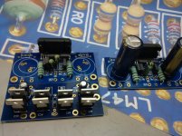
This is the only current picture I have of the power supply board, you can see everything that is on it, just 8 diodes, 2 47uf caps. I am using a dual 24v transformer into the 4 ac ins. The amp boards resistors are Caddock mk132 22k and 220r, kiwame 680r and the .1% big guys supplied with the kit.
I talked to Peter Daniels, he said to try and lower the value of the shunt resistor on the input from 22k down to 10/11k. Maybe because it is direct coupled, the impedance of my signal from the interface is still a bit high
I talked to Peter Daniels, he said to try and lower the value of the shunt resistor on the input from 22k down to 10/11k. Maybe because it is direct coupled, the impedance of my signal from the interface is still a bit high
The way I built the kit:
1. 4700uF caps on the PS boards
2. Zobels on all LM chip outputs
3. 22k Rin, but one for each input - not shared.
I get excellent offset values in every possible mode. I do remember having issues with it initially but after giving each chip its own grounding resistor it was A-OK.
Try Peter's solution, it certainly can't hurt...
Tomchr mentions offset trim.
Find the DC resistance seen by the +IN pin.
Find the DC resistance seen by the -IN pin.
For a perfect opamp/chipamp, setting these two values identical results in a zero output offset.
But opamps are not perfect.
The datasheet tells you the input offset current and the input offset voltage.
You can change the +IN & -IN resistances very slightly to take account of imperfect opamp offsets.
Maybe -IN = 27k and +IN = 26k54, results in zero output offset.
As the opamp heats up the output offset will change. So you decide at what temperature you require least offset.
AC coupled amplifiers are very easy to set up to give near zero output offsets.
DC coupled amplifiers are very different ! Take care. Even adjusting the vol pot can result in enormous changes in output offset in badly designed amplifiers.
I decided I should wait to make any resistance changes until I get the balanced input devices installed that I am waiting on. I also have not connected the. Volume pot in line with the signal yet, so there may be changes.
Andrew T are you talking about matching the resistance of the signal inputs +/- ?
Sorry I'm not that technically inclined when it comes to circuits and how they work intrinsically I would love to fully understand all that stuff though
Andrew T are you talking about matching the resistance of the signal inputs +/- ?
Sorry I'm not that technically inclined when it comes to circuits and how they work intrinsically I would love to fully understand all that stuff though
Yes, the output offset of a perfect (BJT input) opamp would be zero if the two +IN, -IN, resistances were exactly equal............Andrew T are you talking about matching the resistance of the signal inputs +/- ?............
That gives one the starting point for obtaining a lowish output offset.
Trimming comes after powering it ON.
You measure the output error.
Then make a small adjustment to ONE resistance. Remeasure and see if you went in the correct direction, or the incorrect direction. Then adjust again and remeasure.
I apologize in advance if this next question sounds very noobish, but how would I go about measuring the difference? With the amplifier off, I would measure the in+ with respect to ground and check it's resistance, and then separately check the in- the same and then compare?
Do you need some kind of steady state test signal from the interface output to test with?
Do you need some kind of steady state test signal from the interface output to test with?
The normal method with an AC coupled amplifer is to remove the spealer load and short the input signal hot to signal return/cold.
Then measure the output offset in mVdc
But a DC coupled amplifier behaves very differently and changes output offset depending on what is connected to the input.
The resistors are read off the schematic.
Then measure the output offset in mVdc
But a DC coupled amplifier behaves very differently and changes output offset depending on what is connected to the input.
The resistors are read off the schematic.
So it may be a better option since this amplifier is dc coupled to try lowering the resistance on the input to help the dynamic offset situation.
Update: I got the balanced input signal boards installed an everything tuned for maximum smoke. Turned it on with the speakers connected, checked the DC offset without an input, it was 150 mv on both amps.
Can someone explain the implications of changing the input resistance values to be lower? Right now there are 22k resistors being shared by each input to the chips. Peter Daniels suggested lowering it to half with another 22k. How would this affect the output offset? Would it alter the sound quality of the amp?
Obviously, if it works, there will be better dynamics to the speaker output having less offset, but how and why?
In my rose tinted and blinkered view you should convert to AC coupled input with a DC blocking capacitor in the feedback lower leg.
Then all you input and output offset problems go away.
Make the input cap F-3dB ~2Hz and add an RF filter with F-3dB ~200kHz.
and the feedback leg F-3dB ~1Hz
Then you get exemplary 20Hz to 20kHz performance.
Then all you input and output offset problems go away.
Make the input cap F-3dB ~2Hz and add an RF filter with F-3dB ~200kHz.
and the feedback leg F-3dB ~1Hz
Then you get exemplary 20Hz to 20kHz performance.
- Status
- Not open for further replies.
- Home
- Amplifiers
- Chip Amps
- LM 4780 DC offset too high ?