EDIT: THIS IS A 12V SUPPLY USING A 6-0-6 TRANSFORMER OUTPUT 12VAC RECTIFIED TO ABOUT 18VDC//NEWEST PSU DESIGN ON POST #38**
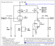
I have put together a simple tube hybrid headphone amplifier per the plans found here -
NP-100v12: DIY 12AU7 (ECC82) Tube / IRF510 MOSFET Headphone Amplifier
I have also put together an LM317 based PSU using the schematic called out in the data sheet. I keep having a buzzing issue no matter which way I hook up the PSU to the amplifier on the breadboard. When I hooked the amplifier up to a 12V battery, the issue disappears.

The buzz sounds like a 120 Hz buzz and is not influenced by the volume of the source. Could it be from the fact that the transformer and PSU are just sitting out in the open? Do I not have enough capacitance in parallel with the output of the rectifier before the IC? Is there an easy to calculate what that value would be? I don't think this can be attributed to the amplifier itself because even when I placed a 100 µF capacitor in parallel with the power input of the amplifier, it did not help. The PSU was built on veroboard and I believe is grounded correctly. Also, the amplifier circuit is star grounded on the breadboard to the PSU outputs.
What is the best way to start troubleshooting these issues? Is there an established "reliable" LM317 design that is any drastic improvement over the one in the datasheet? I would prefer to nail down this design with the LM317 so I can use it for various projects.
Thanks.
I have put together a simple tube hybrid headphone amplifier per the plans found here -
NP-100v12: DIY 12AU7 (ECC82) Tube / IRF510 MOSFET Headphone Amplifier
I have also put together an LM317 based PSU using the schematic called out in the data sheet. I keep having a buzzing issue no matter which way I hook up the PSU to the amplifier on the breadboard. When I hooked the amplifier up to a 12V battery, the issue disappears.
The buzz sounds like a 120 Hz buzz and is not influenced by the volume of the source. Could it be from the fact that the transformer and PSU are just sitting out in the open? Do I not have enough capacitance in parallel with the output of the rectifier before the IC? Is there an easy to calculate what that value would be? I don't think this can be attributed to the amplifier itself because even when I placed a 100 µF capacitor in parallel with the power input of the amplifier, it did not help. The PSU was built on veroboard and I believe is grounded correctly. Also, the amplifier circuit is star grounded on the breadboard to the PSU outputs.
What is the best way to start troubleshooting these issues? Is there an established "reliable" LM317 design that is any drastic improvement over the one in the datasheet? I would prefer to nail down this design with the LM317 so I can use it for various projects.
Thanks.
Attachments
Last edited:
Make sure the input voltage to the 317 is always more than 3V greater than
the output voltage, or it will not regulate, and will pass on any noise in the input.
This includes the minimum voltage dip during each 120Hz rectification cycle.
Also make the filter capacitor after the rectifier large enough to minimize ripple,
probably 1000uF or more. Since this powers the filaments, that could be a noise path.
Last edited:
Make sure the input voltage to the 317 is always more than 3V greater than
the output voltage, or it will not regulate, and will pass on any noise in the input.
This includes the minimum voltage dip during each 120Hz rectification cycle.
Also make the filter capacitor after the rectifier large enough to minimize ripple,
probably 1000uF or more. Since this powers the filaments, that could be a noise path.
My transformer is a 12-0-12 so the first issue shouldn't be it. My output cap between rectifier and IC is 1000uF already. Any other ideas?
Last edited:
Can you post a photo of the construction? You are likely drawing around 1/4 A.
Where the diode block and capacitor are grounded makes a difference.
Are you really using 1N4148 diodes? The 1N4005 would be more suitable.
Where the diode block and capacitor are grounded makes a difference.
Are you really using 1N4148 diodes? The 1N4005 would be more suitable.
Last edited:
My transformer is a 12-0-12 so the first issue shouldn't be it. My output cap between rectifier and IC is 1000uF...
That just-barely meets Rayma's 3V headroom rule, assuming non-heroic transformer.
The line from rectifier (or PT CT) to first cap is full of crap and you can't connect audio along the length of it.
Attachments
Can you post a photo of the construction? You are likely drawing around 1/4 A.
Where the diode block and capacitor are grounded makes a difference.
Are you really using 1N4148 diodes? The 1N4005 would be more suitable.
I am using a 1N4007 and outputting 12.6V. I have the corrected schematics attached and below. I will post a construction picture later. The diodes are grounded right next to each other and the cap is right there.

That just-barely meets Rayma's 3V headroom rule, assuming non-heroic transformer.
The line from rectifier (or PT CT) to first cap is full of crap and you can't connect audio along the length of it.
Saw that and corrected the schematic. Headroom should not be the issue. What do you mean by your second comment?
How do you get the values you put in for the load and does that software calculate different for a full bridge rectifier? Does that matter? Just curious.
Over 3V of ripple, so that's probably it. MORE CAP! At least 3300uF.
At the input of the IC or at the output?
Attachments
Replace R3 with a 2k2 and all is fine.
Mona
I tried with a 2k2 and still have the ripple issue. The output is a dead on 12.6V in the actual circuit.
That little amplifier has really poor PSRR. Figure with an LM317 you have 60dB of PSRR, so 4V pk-pk ripple is 4mV times gain on the output. (Edit -- the current drawn through the LM317 is 150mA for the filament and 2 x 125mA for the two class-A output stages.)
btw, WJ pointed out that the LM317 is a noisy current source/sink -- this in response to letters written after the "Sources 101" articles were published in AudioXpress a few years ago.
btw, WJ pointed out that the LM317 is a noisy current source/sink -- this in response to letters written after the "Sources 101" articles were published in AudioXpress a few years ago.
Last edited:
With R1 - R3 = 240Ω - 3k55 the LM317 try to get an output of 19,5V.
With 220Ω - 3k7 an output of 22V.
In both cases there is no voltage left for the stabiliser, the ripple from C1 is past to the output.
If, with 240Ω - 2k2 for a 12V out, there is still a ripple on the output the C1 is to small or the output from the transformer (loaded) is to low.
Mona
With 220Ω - 3k7 an output of 22V.
In both cases there is no voltage left for the stabiliser, the ripple from C1 is past to the output.
If, with 240Ω - 2k2 for a 12V out, there is still a ripple on the output the C1 is to small or the output from the transformer (loaded) is to low.
Mona
If I need regulated 12VDC from 12VAC I use either Shottky diodes in a bridge or low-drop regulators (LD1086V for example), or both ways together.
Unfortunately, LM317 can't make well regulated 12VDC from 12VAC.
Unfortunately, LM317 can't make well regulated 12VDC from 12VAC.
Last edited:
If I need regulated 12VDC from 12VAC I use either Shottky diodes in a bridge or low-drop regulators (LD1086V for example), or both ways together.
Unfortunately, LM317 can't make well regulated 12VDC from 12VAC.
Do you have a schematic for that? Also why is the LM317 poor for noise with a 12VAC transformer?
That just-barely meets Rayma's 3V headroom rule, assuming non-heroic transformer.
The line from rectifier (or PT CT) to first cap is full of crap and you can't connect audio along the length of it.
My mistake again I am using the outputs of a 6-0-6 to rectify 12VAC
...outputting 12.6V. I have the corrected schematics attached and below. ... full bridge rectifier? ...
Have you *measured* 12.6V output? Loaded?
Where did you get that rectifier? It sure is not a typical "full wave bridge". It is a double doubler. Counting on thumbs it should make 35V of DC but be highly sensitive to source resistance. With some source resistance and a load, my sim drops to 10V DC.
Attachments
FWIW, your C5 C6 appear to get a complete reversal of voltage polarity every cycle, perhaps 5V the wrong way. Electrolytics will not stand this for very long.
The doubler should not do this; the current is too large for your 220u caps. However you do not need these caps AT ALL.
Full-wave DC power supply
https://terpconnect.umd.edu/~toh/ElectroSim/FullWave.GIF
The doubler should not do this; the current is too large for your 220u caps. However you do not need these caps AT ALL.
Full-wave DC power supply
https://terpconnect.umd.edu/~toh/ElectroSim/FullWave.GIF
Attachments

Have you *measured* 12.6V output? Loaded?
Where did you get that rectifier? It sure is not a typical "full wave bridge". It is a double doubler. Counting on thumbs it should make 35V of DC but be highly sensitive to source resistance. With some source resistance and a load, my sim drops to 10V DC.
I have measured that output loaded. My mistake again, I have too many files floating around and gave up the wrong diagram. Please have a look at the new one.
FWIW, your C5 C6 appear to get a complete reversal of voltage polarity every cycle, perhaps 5V the wrong way. Electrolytics will not stand this for very long.
The doubler should not do this; the current is too large for your 220u caps. However you do not need these caps AT ALL.
Full-wave DC power supply
https://terpconnect.umd.edu/~toh/ElectroSim/FullWave.GIF
Again, wrong PSU schematic. If you don't mind I would still love help with this.

Over 3V of ripple, so that's probably it. MORE CAP! At least 3300uF.
Would this work with 3300 uF and no other adjustments?
Attachments
1) No, sorry.Do you have a schematic for that? Also why is the LM317 poor for noise with a 12VAC transformer?
2) Datasheet, calculations, and measurements (I'm talking about a 'full bridge rectifier'). LM317 works well with at least 3,5 V across it.
Last edited:
1) No, sorry.
2) Datasheet, calculations, and measurements (I'm talking about a 'full bridge rectifier'). LM317 works well with at least 3,5 V across it.
Fair enough but my after bridge voltage satisfies that requirement I think?
- Home
- Amplifiers
- Power Supplies
- LM 317 Buzz Issue/Design