AndrewT said:
Maybe this would have benefited from a slow charge circuit.
Or a 35 amp bridge.
I'll not play with 540x for rectifier duty anymore - better to be safe than sorry. Luckily, I was around when it happened and the transformer wasn't damaged.
fr1s said:
I guess it's better now 🙂 Yea if you think, you're right it's more flexible I can change the capacitance if I want.
Hi,
Recommend a better bridge:
An externally hosted image should be here but it was not working when we last tested it.
About the same price as 4 of the 1N540x. 20 amps, 1000V.
GBJ1510
MJL21193 said:
Or a 35 amp bridge.
I'll not play with 540x for rectifier duty anymore - better to be safe than sorry. Luckily, I was around when it happened and the transformer wasn't damaged.
aww 🙁 that sux
MJL21193 said:
Hi,
Recommend a better bridge:
An externally hosted image should be here but it was not working when we last tested it.
About the same price as 4 of the 1N540x. 20 amps, 1000V.
GBJ1510
OK looks good too me 🙂
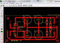
An externally hosted image should be here but it was not working when we last tested it.
Did I connected the diode right way? I'm not really sure, looks ok to me.
fr1s said:
Did I connected the diode right way? I'm not really sure, looks ok to me.
The 2 centre pins are AC, the outer are + and -. Also, the pin spacing is 10mm - 7.5mm - 7.5mm with the 10mm space between the + pin and AC1.
Attachments

What is the purpose of the school project?
Should you show that you can put into practice, what you were taught and that you can design and build a working amplifier?
Or should you show that you follow other people's component choices and that you think it will sound better that way without any possibility to proove it?
Do your own calculations to find out, which demands your components have to meet. Make your own decision about, which components can cope with the demands, and take into account that in real life you also have to deal with limited budget, ease of mounting and maintenance, tolerances and so on. Make sure that you can explain to your teachers, why you chose a certain component for a certain task. "Because somebody else uses it" is not a convincing explanation. Take safety margins into account, but don't use components that are far oversized without a good reason.
E. g. use the 1N5401, if you already have them and find that they can cope with the two amplifier channels. Use an 8 A rectifier bridge, if it is cheaper and easier to implement. Use a 35 A rectifier bridge, if the price difference is small, but the advantages in mounting, maintenance or reliability justify that choice. Use MUR860 for your hobby, not for your school project.
Show that you know, how to apply Ohm's, Kirchhof's and Newton's laws to determine your power supply demands. Show that you learned, what transformer regulation is and how it is important for your project. Show that you learned, how to calculate a capacitor for adequate ripple rejection. Show that you know, how to calculate adequate heatsinks. Show initiative by researching the mains fluctuation for the zone, where you live and how it is important for your project. Explain, why you chose the LM1875 for this amplifier. Don't get carried away with nice-to-have's like VU meters or sound improvements through bigger smoothing capacity. Keep in mind that you have to present your project in a limited amount of written pages or speaking time to convince your teachers that it deserves a good mark. Don't forget that your teachers may have different ideas about the usefulness of such a project than you.
250mW resistor would do.
Some 600mW resistors are the same length as 250mW ones. Use 0.3inch pin pitch for all your resistors.
Check the pin pitch of the rectifier.
What setting have you got for the grid dots in the PCB software?
What setting have you got for the snap to grid?
Have you got snap set to off?
Some 600mW resistors are the same length as 250mW ones. Use 0.3inch pin pitch for all your resistors.
Check the pin pitch of the rectifier.
What setting have you got for the grid dots in the PCB software?
What setting have you got for the snap to grid?
Have you got snap set to off?
good advice.pacificblue said:What is the purpose of the school project?.....................to convince your teachers that it deserves a good mark. Don't forget that your teachers may have different ideas about the usefulness of such a project than you.
- Status
- Not open for further replies.
- Home
- Amplifiers
- Chip Amps
- Lm 1875 problem? :(