Sorry for double post. I forgot to mention that I'm building this for 8ohm speakers and I might use 30v transformer, I haven't decided which one to use.
Bring the two groups of three input/output connections to 0.2inch pitch. It allows use of three way terminal blocks or soldered joints.
Leave lots of space around the 4 caps just in case you want to use 40mm diameter.
Squeeze everything else closer to reduce the size of the PCB.
Increase the width of the high current traces by a factor of 4.
Add an optional snubber R + C across each diode.
Add a snubber R + C across the output.
Add a cap from AC to AC to absorb glitches/pulses coming from the transformer.
Think about adding pads for a resistor in each feed line both before and after the first capacitor. That's 4pair of pads. These pads can be for thermistors and/or inductors and/or resistors. This makes for a very multi-purpose PCB.
30Vac sounds a bit (lot?) high for an 8ohm load.fr1s said:I'm building this for 8ohm speakers and I might use 30v transformer.
30Vac can give >48Vdc if mains is running at +6% and the regulation is 10%.
Or, do you mean 30Vac centre tapped which is equivalent to 15-0-15Vac?
here u go 🙂
I found some 1n5401 diodes @ home, are they ok for this?
Also I found out that they are 3A, does that mean that on out put each of my amp's gonna get 3 A or just 1.5?
So if I'm gonna use these diodes does, do I have to get
"3A" +25 0 -25 transformer? (I'm gonna use 25v)
thx for help 🙂
An externally hosted image should be here but it was not working when we last tested it.
I found some 1n5401 diodes @ home, are they ok for this?
Also I found out that they are 3A, does that mean that on out put each of my amp's gonna get 3 A or just 1.5?
So if I'm gonna use these diodes does, do I have to get
"3A" +25 0 -25 transformer? (I'm gonna use 25v)
thx for help 🙂
You get, what your amps ask. If the sum is more than 3 A for more than a few ms those diodes will blow.fr1s said:Also I found out that they are 3A, does that mean that on out put each of my amp's gonna get 3 A or just 1.5?
Did you read the datasheet? Max rail voltage is 60 V or ±30 V. How much is 25 V times 1,41 plus regulation plus mains fluctutation?fr1s said:So if I'm gonna use these diodes does, do I have to get
"3A" +25 0 -25 transformer? (I'm gonna use 25v)
Well I guess I cant use em :/ that's ok extra few cents for 4 diodes wont hurt me.
ok pacificblue, so which diodes should I use then? maybe you can help me with transformer too?
Sorry I'm a bit of noob, I'm only 17 building my first chip amp 😎
ok pacificblue, so which diodes should I use then? maybe you can help me with transformer too?
Sorry I'm a bit of noob, I'm only 17 building my first chip amp 😎
So you do expect more than 3 A?
Start with reading the datasheet.
To make a nominal 20 W amplifier you need ~±22 V loaded with 8 Ohm speakers or ~±18 V loaded with 4 Ohm speakers.
That is ±25-26 V unloaded -> a 2*18 V transformer 1,6 A per channel for 8 Ohm or ±21-22 V unloaded -> a 2*15 V transformer 2,25 A per channel for 4 Ohm.
Use a transformer with 80-120 VA for a stereo amplifier. 40 VA would be enough, but has too high regulation.
Check: 2*18 V +25% safety margin for regulation and mains fluctuation times 1,41 minus 1,4 V diode drop = 30,3 V. One percent overvoltage at no load should be acceptable for a worst case assumption.
The 1N5401 will be okay, because a normal music signal will not lead to peaks that surpass 3 A for long enough to destroy them. Use them, if you already have them.
A good alternative would be a bridge rectifier. It is easier to connect compared to single diodes, thus avoids wrong connections. E. g. something like this.
Well I guess I have to go do some parts shopping. 🙂
yea I wanna be a little bit more safe so I might go with more A.
I see BrianGT kits use 8A diodes MUR860 I guess those wont hurt me?
yea I wanna be a little bit more safe so I might go with more A.
I see BrianGT kits use 8A diodes MUR860 I guess those wont hurt me?
Dorry for double post but yea I might get my two VU connected to that power supply so i wound need probably more then 3A.
Hi,
I have four power amps that use 1n5404s as the bridge rectifier.
They charge up 20mF to 80Vdc.
None has ever blown.
I have four power amps that use 1n5404s as the bridge rectifier.
They charge up 20mF to 80Vdc.
None has ever blown.
Hi!
Is there any difference between 1n5404 and 1n5401?
I checked the data sheets and it looks the same to me?
Is there any difference between 1n5404 and 1n5401?
I checked the data sheets and it looks the same to me?
hello.
01 = 100volt maximum
04 = 400v max.
useful toy that lm 3915 n .
i think i will build that too.........
greetings........
01 = 100volt maximum
04 = 400v max.
useful toy that lm 3915 n .
i think i will build that too.........
greetings........
mjf said:hello.
01 = 100volt maximum
04 = 400v max.
useful toy that lm 3915 n .
i think i will build that too.........
greetings........
yea 3915 or 16 are fun 🙂 took me 20 minutes to put both of them on breadboard
got the schematics from this site
VU meter schematics
AndrewT said:Hi,
I have four power amps that use 1n5404s as the bridge rectifier.
They charge up 20mF to 80Vdc.
None has ever blown.
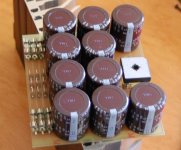
I had two of the four 5406's short on power up in this power supply board. I switched to a 35 amp bridge.
Attachments
post25.
why have you deleted half the capacitance?
As it was is far superior and particularly, more flexible if you add the extra resistors/inductors as suggested.
why have you deleted half the capacitance?
As it was is far superior and particularly, more flexible if you add the extra resistors/inductors as suggested.
is that 47mF charged to <80Vdc from one 1n5406 bridge?MJL21193 said:I had two of the four 5406's short on power up in this power supply board. I switched to a 35 amp bridge.
Maybe this would have benefited from a slow charge circuit.
An externally hosted image should be here but it was not working when we last tested it.
I guess it's better now 🙂 Yea if you think, you're right it's more flexible I can change the capacitance if I want.
- Status
- Not open for further replies.
- Home
- Amplifiers
- Chip Amps
- Lm 1875 problem? :(