This scheme should not be assessed as sounding by ear at the low end, because The input stages of this circuit have significant gain nonlinearity in the audio frequency range. Simply put, the input stage has hyperboost at punchy low frequencies, approximately +14dB at 40Hz relative to 1kHz. The Miller correction eliminates any gain at 20kHz for the input stage before embracing negative feedback. The main quality in this circuit is played by the driver transistor (2nd in a row), but it operates in a not very good operating current for high-quality control of the Shiklai output stage.So I've seen a few posts suggesting that the input cap C1 is not sufficient value for proper bass response. In running a freq. sweep below 200Hz with an 8 Ohm load, I'm not seeing the issue that some claim nor do I hear it!
Last edited:
You are misleading with your speculation about the sound quality of this amplifier. The circuit needs significant improvements to the DC modes and progressive frequency correction.They were clear, articulate, mids sounded well-balanced, and the bass punched with the authority for an ~80ish wpc amp. BTW, they are dead silent when the music paused with ear up to the speaker. For $14USD each, I'd say, you couldn't ask for much more.
Apparently, unfortunately, LJM does not have enough knowledge to improve the sound of this rather simple topology, so the sound for $14 will remain the same. It may sound unusual, but that's what $14 sounds like...

Calvin,Hi,
what's the type of SMPS You're using in the pics?
jauu
Calvin
sorry for the intrusion on this post, but I have sent you a message few days ago regarding a problem with the buffer you designed. Could you please check my message and reply when you get a chance?
Thanks,
Stefano.
Hi Raj!
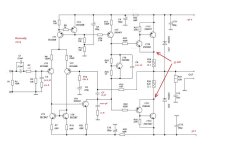
The simplest modification of the finished amplifier has been done now, see attachment.
At first glance, the values of the correction capacitors are very large, but this is in order to improve the quality of operation of the Shiklai output stages in the AB class. The unity gain frequency is 1.8 MHz, the slew rate is 4 V/µs - this is enough for high-quality sound reproduction. Distortion at a frequency of 20 kHz at maximum output power into a 4-ohm load does not exceed 0.0016%.
C1 increased by doubling capacity
R2 increased to 2 kОhm
C2 is a capacitance of 1500pF + a 200 Ohm resistor
R13 is increased to 680 ohms, the gain will be 22 dB
C7 is reduced to 10 pf and reconnected to the base of the transistor in the diffcascade
The driver transistor VT9 is loaded onto a 1000pF + 10 Ohm RC circuit to eliminate the progression of higher harmonics from the Shyklai cascade.
C9 has been changed to a capacity of 0.22 microfarads; a large-capacity electrolyte cannot be placed there (for example, 47 uF), because the output stage operates in class AB.
The initial current of the output stage is 180mA, which can be adjusted by slightly reducing resistor R20 (approximately 950-980 ohms). If you make a smaller initial current in Shiklai, the quality of sound reproduction will suffer.
Attachments
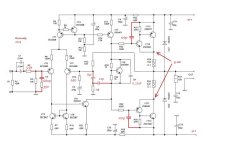
For those who asked in letters for a second-order compensation option for MX50 kit, see attachment.
applied Butterworth coefficients, highlighted the compensation circuits in red, replaced R13 and C9 with the nominal value indicated in the diagram in the attachment.
The compensation feature is that distortion is practically independent of frequency, and maximum linearity of the input stage and open loop gain.
Attachments
Sorry, not seeing any non-literariness on the scope in the 30 to 200Hz range past the initial input stages or at the output. Show me your o-scope results or pertinent data. This is a pretty flat amp. up and down the scale. Period!This scheme should not be assessed as sounding by ear at the low end, because The input stages of this circuit have significant gain nonlinearity in the audio frequency range. Simply put, the input stage has hyperboost at punchy low frequencies, approximately +14dB at 40Hz relative to 1kHz. The Miller correction eliminates any gain at 20kHz for the input stage before embracing negative feedback. The main quality in this circuit is played by the driver transistor (2nd in a row), but it operates in a not very good operating current for high-quality control of the Shiklai output stage.
the context was for amplification of the open loop input stage in this range.Sorry, not seeing any non-literariness on the scope in the 30 to 200Hz range past the initial input stages or at the output.

This is no longer visible at the amplifier output. And what does "flat" mean? An input stage with Miller compensation cannot have a “flat frequency response open loop”This is a pretty flat amp. up and down the scale.
Last edited:
This version of modified compensation sounds very good. Still, the lack of dependence of the distortion level on frequency has its advantages.
https://www.diyaudio.com/community/threads/ljm-mx50-kit-amp.216609/post-7626144
https://www.diyaudio.com/community/threads/ljm-mx50-kit-amp.216609/post-7626144
Hello everyone!! I decided to try two boards of this famous amplifier...which version do you recommend? I saw this one with the SanKen "Lusya 2pcs MX50 SE SANKEN" on Aliexpress....what do you think? Are the SanKen definitely fake? Or does anyone have a specific seller/model to recommend? I have a linear power supply from +/-42V DC thanks
I'm seeing that the most recent SanKen pair that replaced the ones in the kit are the 2SC3263 + 2SA1294...I think I'll get the kit with the KEC finals (which I won't use) and then put these latest SK ones in there...
Hello guys!! I'm listening to the pair of MX50SE cards with 2SC3263 + 2SA1294 power amps, I was pleasantly impressed!! What a beautiful sound, what a soundstage!! I used them to rejuvenate a Sony integrated amplifier, the TA-S7 model that I have had a faulty model for a long time, and which turned out to be perfect for bringing in two cards powered at +/-42V and driven directly by the existing motorized ALPS volume, in addition to using the zobel network and the output protection with relay and uPC1237 ... an exceptional result!! all the functions of the integrated amplifier but with new power amps 🙂


So, is it considered safe/good practice to double up on the output transistors in this design?
I ordered a pair of kits yesterday with the ambition to use one board to build a mono amp that can drive 4 ohms safely with +-42V rails (in retrospect I should have bought the L12 kits instead but it is what it is). This is for subwoofer duty and I have a 30-0-30VAC toroid with an extra 12-0-12V winding (low current for filter/preamp) that I would like to use. I also have several pairs of 2SA1215/2SC2921 (genuine Sanken, pulls from an old pro amp that was scrapped) and a large heatsink with tapped screw holes for two pairs of said transistors.
I ordered a pair of kits yesterday with the ambition to use one board to build a mono amp that can drive 4 ohms safely with +-42V rails (in retrospect I should have bought the L12 kits instead but it is what it is). This is for subwoofer duty and I have a 30-0-30VAC toroid with an extra 12-0-12V winding (low current for filter/preamp) that I would like to use. I also have several pairs of 2SA1215/2SC2921 (genuine Sanken, pulls from an old pro amp that was scrapped) and a large heatsink with tapped screw holes for two pairs of said transistors.
KEC KTB817。 Alternatively, ONS EMI NJW0302G would suffice. They are very cheap. There is no difference in effect either.
The Sanken power transistor only has an additional copper plate on the back. Actually, there won't be any difference., The price has doubled.
The Sanken power transistor only has an additional copper plate on the back. Actually, there won't be any difference., The price has doubled.
KEC KTB817。 Alternatively, ONS EMI NJW0302G would suffice. They are very cheap. There is no difference in effect either.Hi, I just received the mx50 se kit if I wanted to change the original output device which best sanken do you recommend? I read several numbers but I don't know which is the best. Thanks
The Sanken power transistor only has an additional copper plate on the back. Actually, there won't be any difference., The price has doubled.
Attachments

no
Measurement. Adjust the static current of ADJ. It refers to the second foot of B817. Voltage between OUT.
Measurement. Adjust the static current of ADJ. It refers to the second foot of B817. Voltage between OUT.
noOK LJM then I leave D1047 and B817 which are standard in the kit. Another thing to check the bias (3mV/0.10 Ohm) I have to connect +Out to the emitter of the B649 with the DMM ok? Thanks again
Measurement. Adjust the static current of ADJ. It refers to the second foot of B817. Voltage between OUT.
- Home
- Amplifiers
- Solid State
- LJM MX50 kit amp