120 KHz -3 dB is it good, and also it is good at 20Hz? I understand this is about very powerful and large transformers. I just now have such a project on four EL509 per channel with a toroidal magnetic core D=204мм, d=140мм, h=70мм of nanocrystalline alloy 5BDSRWhat are you talking about?
I already demonstrated pictures of oscillograms of an amp that produces up to 120 KHz -3 dB on full power on nominal load, using cheap Edcor transformer. Is not it enough?
Is there a Litz wire in a fabric braid such as silk or polyester?
Last edited:
Is there a Litz wire in a fabric braid such as silk or polyester?
Yes:
P A C K - F e i n d r h t e - Cost efficient Safety Components with RUPALIT Systems
Aren't we wandering a bit off topic guys in the meantime?? 😱😱
I do not think so, (almost) all cited examples are SE OPT with standard magnet wire, not Litzendraht wire.
If the use of Litzendraht wire where such a great idea let's advise to Tango, Hashimoto, Tamura...
Apparently the marketer Рartridge was not able to hear through your amplifier with a transformer with a gap that records are cut LP perfectly and without any sort of gap in the magnetic circuit.
https://www.youtube.com/watch?v=6wmfyq2HD20
http://www.technicalaudio.com/pdf/G...Audio_Developments_feedback_cutter_system.pdf
With all due respect, you did not make any difference between mains power transformers and output audio transformers, and now you are introducing LP cutting heads into the discussion? 😕
About gapless SE opt: think of parafeed 🙂
You are right, anyway I do not consider such engendros in the SE category. 😀
On the other hand, besides toroids, the only gapless core I know is the power transformer of a microwave oven, the gap is a solid solder...
Thank you! Since you are from Holland still an issue to you, perhaps you know what material in the magnetic circuit is used by Menno van der Veen.
Thanks for the link, Peter !
What are you talking about?
I already demonstrated pictures of oscillograms of an amp that produces up to 120 KHz -3 dB on full power on nominal load, using cheap Edcor transformer. Is not it enough?
For 5W output power using a small trnasformer it's easy to satify all conditions just using normal wire and proper winding scheme (not even too complicated). Not so much with BIG power. That's the point.

You are an intolerable debater. Now I understand the story of "Meeting" by Jorge Luis Borges even better. You again and again look at the link of the GOTHAM PFB-150WA Power Amplifier. To reduce distortion, US engineers used a toroidal magnetic core without cuts.which not only perfectly cuts, master discs, but also plays music with acoustic systems, Partridge could not even dream about it!🙄With all due respect, you did not make any difference between mains power transformers and output audio transformers, and now you are introducing LP cutting heads into the discussion? 😕.
https://www.youtube.com/watch?v=6wmfyq2HD20
http://www.technicalaudio.com/pdf/G...Audio_Developments_feedback_cutter_system.pdf
Last edited:
Hi
1- the Litz trafo I have is:
double C core, 0,1 mm laminated, M0, V51 ( HWR table), weight of about 1 kg each C core.
primary: 1784 (my error) turn divided in 4 section, 446 turn each one, the wire is 10 strand, 0,31 mm diam. total, certified up to 700 volt, for each section there is a foil of mylar of 0,05mm thick
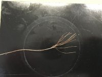
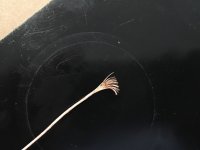
photo 1 the wire
secondary: 85 turn, wire 50x 0,1 mm diam., 3 section in parallel; intercalated with primary
photo 2 the wire
Rdc of 92 ohm.
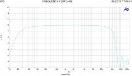
In photo 3 a freq. answer of a s.e. with ECC81+KT880 no FB and Litz trafo, 8 watt on 8 ohm, - 3dB at around 65 KHz; a low freq. the answer is acceptable ( the new one is coming with better L)
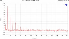
On photo 4t he FFT at 1 w
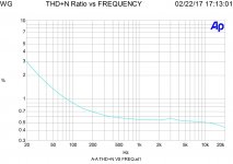
On photo 5 the THD vs frequency.
I stop here for the moment
Walter
1- the Litz trafo I have is:
double C core, 0,1 mm laminated, M0, V51 ( HWR table), weight of about 1 kg each C core.
primary: 1784 (my error) turn divided in 4 section, 446 turn each one, the wire is 10 strand, 0,31 mm diam. total, certified up to 700 volt, for each section there is a foil of mylar of 0,05mm thick
photo 1 the wire
secondary: 85 turn, wire 50x 0,1 mm diam., 3 section in parallel; intercalated with primary
photo 2 the wire
Rdc of 92 ohm.
In photo 3 a freq. answer of a s.e. with ECC81+KT880 no FB and Litz trafo, 8 watt on 8 ohm, - 3dB at around 65 KHz; a low freq. the answer is acceptable ( the new one is coming with better L)
On photo 4t he FFT at 1 w
On photo 5 the THD vs frequency.
I stop here for the moment
Walter
Attachments
Last edited:
for each section there is a foil of mylar of 0,05mm thick
So, that you gain (if any) with Litzendraht wire you lose it with capacitance due to insulation... with all due respect you are wasting your money...
Edit: 446 x 4 = 1784
Last edited:
Don't worry, are my money.
Please let us know your test, thanks. I never seen one from you until today, only formulas.
In addition, finally you have learned another method to test the trafos (post 4) , are you lucky?
Walter
Please let us know your test, thanks. I never seen one from you until today, only formulas.
In addition, finally you have learned another method to test the trafos (post 4) , are you lucky?
Walter
Last edited:
But they only offer up to 0.5mm. Not worth using for most AUDIO output transformers, IMHO. They are only useful for RF......
Generally speaking, one might think to switch to Litz when the required size gets close to 1 mm or more (depending on all other parameters). I have never used 1 mm secondary wire even for a 60W PP OT amp made for a classic Dynakit with KT88. In that case I used a 0.56 mm wire for the secondary (about 0.63 mm with insulation) getting an increase in AC resistance @ 20KHz of just 15% respect to DC.
The amp of Mr. Wavebourn has a feedback, as he told.
So what? Full power means losses on 100 KHz are the same as losses on 1 KHz, is there feedback, or no feedback. -3 dB on 120 KHz is caused by stray inductance and parasitic capacitances. If there is some skin effect, it is absolutely negligible.
We live in 21'St Century, when people know math and can calculate nested feedback loops for wider band and better stability in 2-stage amp.
120 KHz -3 dB is it good, and also it is good at 20Hz? I understand this is about very powerful and large transformers.
Yes, from 20 Hz, but for 5W output power. For higher power we should think of layering and sectioning, because stray inductance and parasitic capacitances are variables that really affect the top frequency end, not dust fairies running around.
Last edited:
The amp of Mr. Wavebourn has a feedback, as he told.
Walter
Walter, even without feedback you can achieve great results with small transformers at low power.
Litz wire becomes useful when you need to use a wire size that is larger than the so called critical diameter imposed by skin effect and proximity effect.
How much is FB?
Have yoy the freq. answer without it?
Only in this case we can have something to discuss about your amp
Help also the THD vs frequency.
"" If there is some skin effect, it is absolutely negligible."
I am trying to check this, if you have te test please let me know, thanks.
Walter
Have yoy the freq. answer without it?
Only in this case we can have something to discuss about your amp
Help also the THD vs frequency.
"" If there is some skin effect, it is absolutely negligible."
I am trying to check this, if you have te test please let me know, thanks.
Walter
45,
I agree with you but we are speaking around the trafo not the entire amp FB included.
Are two different things
Ciao
Walter
I agree with you but we are speaking around the trafo not the entire amp FB included.
Are two different things
Ciao
Walter
"" If there is some skin effect, it is absolutely negligible."
I am trying to check this, if you have te test please let me know, thanks.
Try to use identical bobbins and iron, identical layering, the same numbers of turns, the same wire insulation, it is called trying. Otherwise you are cheating yourself.
How much is FB?
As I said before, it does not matter. Power loss in transformer can not be compensated by any FB.
Yes, from 20 Hz, but for 5W output power. For higher power we should think of layering and sectioning, because stray inductance and parasitic capacitances are variables that really affect the top frequency end, not dust fairies running around.
If one wants to optimize the size of the core, optimize the winding geometry, minimize losses not every layering and sectioning is possible. Actually there just few solutions. As I said above, I accepeted 15% increase of AC resistance at 20KHz by using a wire (0.56mm) that was a bit bigger than the critical diamater (of about 0.67 mm for that transformer). However one has to see case by case. There is no magic number and everything is not possible if there are contrasting conditions.
My client insists on using flat copper enameled wire in the secondary winding. And the simplest partitioning. I thought about using two spaced secondary windings connected in parallel, аs in transformers TRIAD.Walter, even without feedback you can achieve great results with small transformers at low power.
Litz wire becomes useful when you need to use a wire size that is larger than the so called critical diameter imposed by skin effect and proximity effect.
???????????? ???? - Triad DATA
Last edited:
Don't worry, are my money.
Please let us know your test, thanks.
Your money, your thread, your transformer, your test... 😀
- Status
- Not open for further replies.
- Home
- Amplifiers
- Tubes / Valves
- LITZ output trafo