Hi all
I did built a two way speaker using the monacor SPH13c as mid bass and a Monacor DT254 as Tw
I used a second order cross over (around 1800Hz) with an L pad on the TW
The speaker sound pretty good and over all I am happy with it but finally I get some (hobby) gear to measure the frequency response and also I learn a bit to use XSim
So simulating the system there is a few Db deep just at cross over frequency and this is confirmed by in room measurement .Nothing dramatic but it is there!(changing polarity on the TW make it much worse)
I just cannot avoid it. The only scenario I can simulate were the response is much better almost perfect is if i use the same L Pad and second order filter but moving the cross over point very low. Lets say 1.2K.
Now the Tw Fs is 900Hz so in theory it is possible but what are the implication of doing this?
Thank you for help🙂
raise the crossover freq. on your mid-bass filter a little, perhaps it's as simple as putting a resistor in series with the capacitor.
Forget the simulations, it's too late for that, use your ears & room measurements
Forget the simulations, it's too late for that, use your ears & room measurements
Hi
Thank you both for replay
As you may understand i am a beginner
I attach what I measured to give an idea
It is not dramatic and they sound very good to me
But this project is also a learning experience
Because the new simulation with a very low cross over cut (1000/1200Hz) looks much better in terms of linearity (increasing make it worse)
i was interested to learn what could happen if i lower the cross over point
(always in the declared working range)
could the TW be damage ? Increase in distortion?
Thank you
Attachments
As you say, the resonant frequency of the tweeter is 900Hz. However, note that Monacor recommends a minimum crossover frequency of 2,000Hz using a 12dB/octave, 2nd order high pass filter.could the TW be damage ? Increase in distortion?
Your present 1,800Hz crossover means that the level will be 12dB down at the tweeter resonance of 900Hz. That is a minimum requirement, and I would not consider crossing over any lower than 1,800Hz. Most designers agree crossing the tweeter more than 1 octave above its resonant frequency helps produce the smoothest response.
A lower crossover point of 1,000/1,200Hz is indeed likely to introduce distortion or damage the tweeter at high volume levels.
Better to raise the crossover point of the mid/bass driver as suggested by Pete.
Thanks Galu
Understand the reasons to avoid lower cross over point.
However
The problem appears to be in the mid bass slope that is not smoth as it should be while the Tw seems to be very nice
Increasing the cross point only move the problem at higher frequency
I assume some kind of correction network would be required
I tried with the notch filters included in the xsim but no success probably because of my present capability
Probably adding a mid driver would solve the problem but is too late for this
So I shall try more time but seems I shall need to leave with that...
Thank you again
I also exeprienced that having a little dip around 2-3kHz helps in achieveing a more natural sound (at least for my ear). So striving for totally flat freq. response may not make things better.
You can also try a 3rd or 4th order filter on the tweeter while maintaining 2nd order on the woofer. Theoretically only a 2nd order--2nd order filter sums to flat response, but the speaker voice coils are in different planes (offset), driver impedances are not resistive and the baffle step also has a role, so a textbook filter is bound to have phase errors (not to mention that driver Freq. responses are not flat either). If there's an offset between woofer and tweeter planes, then often a better filter can be found by making the cutoff slopes different on the woofer and tweeter. I had success with 2nd order woofer and 3th order tweeter.
I don't know xsim, does it allow adding the driver sound pressure and impedace curves? Without incorporating these curves, the simulation isn't worth anything. Don't forget to set the tweeter offset (in mm) relative to the woofer. BTW, VituixCAD is a very capable free software (at least a few years ago it was free).
thanks gerenis69
I did not think about the offset. I shall try to make some test
XSim works with FRD and impedance file so the simulation should be decent thought i do not believe it can simulate off set (i am no expert need to check the options).Virtuix cad is still free but it is just to much for me at this stage.
I shall also try an asymmetrical filter as you suggest
If you measure the FRD files yourself, then you know (should know) where you placed the microphone from each of the speakers, so you can calculate the relative offset. But if you use some manufacturer made FRD, you never know how far the mike was when they measured the curves (was the mike at the same distance from the tweeter and woofer?), and was there a different electronical delay between measurement of the tweeter and woofer or not? Electronic delay manifests itself as if there was an offset in distance. Especially if the tweeter and woofer comes from a different manufacturer, you won't have a clue about offset. So factory made FRD files may not be useable for crossover design...
Here is a tutorial to finding the driver offsets using REW and XSim: Speaker acoustic center - How to find it | Audio Judgement
You might also consider attaching your XSim file and let others have a look at it too.
You might also consider attaching your XSim file and let others have a look at it too.
Hello jReave
Thank you I shall read carefully
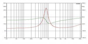
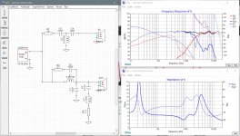
For the moment i attach the XSim (hopefully i did it right!!)file I used and the speakers data I used to create the FRD and impedance file used an asymmetrical filter?
During a last simulation I find that using a third order filter on the mid can help to make the response flatter. Any problem in using
Open to any suggestion
Thank you I shall read carefully
For the moment i attach the XSim (hopefully i did it right!!)file I used and the speakers data I used to create the FRD and impedance file used an asymmetrical filter?
During a last simulation I find that using a third order filter on the mid can help to make the response flatter. Any problem in using
Open to any suggestion
Attachments

Ok so it looks like you are using the above files to do your sims instead of your own measurements of the drivers in the cabinets, which is really what you need to do if you want to get it right.
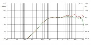
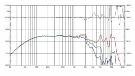
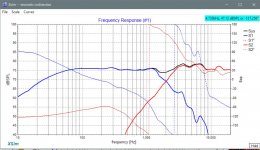
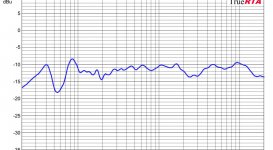
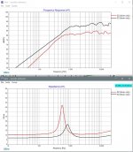
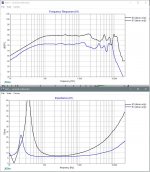
So for eg., the above files don't look like they include the effects of the box on the woofer, the effects of baffle diffraction, the difference in relative acoustic centers between the drivers or the extraction of minimum phase from all the files. So the system response you get in XSim doesn't actually match the measurement you attached in post #4. See pics below. Although they aren't actually too far apart so I'm a touch confused. In XSim, the tweeter is a little hot and the valley you are concerned about is centered slightly lower in frequency than what you measured. Pic 1 is measured; pic 2 is XSim.
If you want to try and accurately measure the in-cabinet responses here is another tutorial on how to do so: Box
In terms of the actual xo, I think the best way to solve your FR problem is going to be the following:
- reduce the value of L1 to fill in that valley near the xo frequency
- you'll get a peak now around 1300Hz which will need to be reduced with a notch filter
- you'll also get a shallower rolloff on the woofer so add a tanking capacitor in parallel to L1 to help increase the rolloff and to reduce the 1st woofer resonance peak
- to get the driver phase to align, I suspect that you may need to go to 3rd order electrical on the tweeter.
I don't expect the values to be correct for the reasons stated above but below is what your XSim files will look like with minimum phase extracted from the files, a guestimate of 1" for the woofer delay and with the above xo changes. I've attached the XSim file as well. Note also how I re-arranged your XSim layout to make it easier to work with and easier to read.
Attachments
Last edited:
Hi jReave
What to say...This is more help the i could expect
Thank you
I have a lot to try here. I shall study Carefully your mod and then shall go for a new filter .
What to say...This is more help the i could expect
Thank you
I have a lot to try here. I shall study Carefully your mod and then shall go for a new filter .
Why don't you try your hand at measuring the drivers in the cabinets before proceeding with a new xo?
Or post the front baffle dimensions and driver positions and let us know about the speaker placement - out in free space on a stand or up against a wall or in a bookshelf, etc. That way we can sim the baffle effects. Maybe net box volume and ported or sealed too?
Or post the front baffle dimensions and driver positions and let us know about the speaker placement - out in free space on a stand or up against a wall or in a bookshelf, etc. That way we can sim the baffle effects. Maybe net box volume and ported or sealed too?
Hi jReave
Well I shall do as you suggest as I get home .At moment I am away for work for few weeks so I can only make plans and simulations for the moment
The speakers are around 14ltrs in volume ported tuned (in theory at 40Hz)
Port is on the rear
The cabinet building is a bit unusual
Front is MDF 18mm with an front layer of 4mm plywood
rear is MDF 18mm
Top and bottom is MDF 18mm
Sides are list of 15mm wood glued vertically and a second row of 5mm wood list glued horizontally
some sheets of tar are glued on the internal wall
The front baffle measurement if I recall properly is around 300mmx250mm
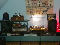
I attach a pictures of the speakers positioning in my room/system (this pictures is all I have with me) so you can see how the speakers are installed on the baffle
I know is not the best room but is my room
The last 20mm at baffle end is angled some 45 degree on both side in attempt to reduce interference
Well I shall do as you suggest as I get home .At moment I am away for work for few weeks so I can only make plans and simulations for the moment
The speakers are around 14ltrs in volume ported tuned (in theory at 40Hz)
Port is on the rear
The cabinet building is a bit unusual
Front is MDF 18mm with an front layer of 4mm plywood
rear is MDF 18mm
Top and bottom is MDF 18mm
Sides are list of 15mm wood glued vertically and a second row of 5mm wood list glued horizontally
some sheets of tar are glued on the internal wall
The front baffle measurement if I recall properly is around 300mmx250mm
I attach a pictures of the speakers positioning in my room/system (this pictures is all I have with me) so you can see how the speakers are installed on the baffle
I know is not the best room but is my room
The last 20mm at baffle end is angled some 45 degree on both side in attempt to reduce interference
Attachments
So it's looking to me like the xo you have implemented doesn't properly take care of baffle diffraction.
So my next question is whether or not you find the speakers slightly bright or slightly out of balance in that the bass isn't quite loud enough?
So my next question is whether or not you find the speakers slightly bright or slightly out of balance in that the bass isn't quite loud enough?
No
Actually I get plenty of bass considering the woofer size
I would say it is a big bass but not as tight as I would like or probably as it should be
but here I believe the room play an important role
No mistake I am happy overall the speakers sound very good to me and I think I made a decent job considering my little experience
The defect I have in my room are
Bass not very tight/clean (a bit of tale)
a certain lack of tridimensional and cleanness in the high mid area that affect the listening experience and here I believe the valley i measure may play a role
The very high frequency are beautiful (I like this TW believe is plenty for the money)
OK, I'm a little surprised that the balance seems right for you because it still doesn't look to me like the speakers have any baffle step compensation. And if the measurement you posted is from the listening position without any gating (which might not be the case, I'm not sure) then the FR should have something of a downward tilt which it doesn't.
Also I took a closer look at your XSim files and I have to say you are 1 lucky novice to have achieved a decent sounding speaker because none of the frd or zma files in the program are accurate traces of the measurements you attached in post #11. Below I've attached a couple of pics comparing your XSim driver files (red and blue) with what I traced from those posted measurements (black). This explains to me now why your XSim mid dip is not in the same place as the measured dip but as I said, you are kind of lucky to have obtained decent results at all.
This also makes the values I used in my XSim inaccurate too because I was using your files as my starting point. So don't use those as a guide either. Best thing to do if you really want to get it right is learn how to take the measurements of the drivers in the cabinets and then we can design the xo from there.
Attachments
Hi jReave
The measure i post is one speaker only at listening point
and
You are right in all count
No baffle step compensation was implemented at software level. Only thing i did was during the building minimize the vertical distance from the speakers
as possible and minimize the area of the baffle as possible a further precaution was to angle the baffle end on the side
You also right ref the frd and zma file accuracy. Fact is i did not have them so i used vituix cad software trace tools to create them and probably they are not perfect due to my lack of experience If you could post yours for me to use i would be grateful
So i suppose you are right also ref the lucky novice (but nothing bad in that)
Yes i definitely need to study little more specially ref the in box measurement
I also thank you for your support and good advice
I have not used the tracing part of VituixCAD yet but it looks to me like you just failed to set the axes parameters correctly which are found in the 4 corners of the program. So just make sure that you input the correct value of wherever you have set up the frequency, amplitude and the impedance lines. A good way to double check is to place the curser in a couple of spots in the graph and make sure the values displayed in the bottom left hand corner of the program are correct. Also, sometimes impedance is charted on a log scale and sometimes on a linear scale. Make sure you choose the right one in the upper right corner. Again checking what the curser values are will tell you if you've got it right or not.
I've attached a new XSim below that includes a number of drivers with different files because your speaker sims only get more interesting (and bizarre) as I go further along. Just move the different drivers around to see the differences. Drivers are labeled. 'Raw FR' means without baffle and box effects added in. You'll just need to unzip the file.
So when I include all the baffle and box and acoustic centers and minimum phase info with the correctly traced frd and zma files, I still do not get the same FR as your measurements. When I change the woofer zma file back to your original incorrect one however, that combination shows the highest correlation to what you measured, and that should not actually be correct so I can't really figure that one out at this point.
But have a play with the new files if you want but a word of caution - I don't necessarily expect the results to be correct in the real world. Again the best thing to do is to measure the real FR and impedance of your speakers in-cabinet and then proceed from there.
I've attached a new XSim below that includes a number of drivers with different files because your speaker sims only get more interesting (and bizarre) as I go further along. Just move the different drivers around to see the differences. Drivers are labeled. 'Raw FR' means without baffle and box effects added in. You'll just need to unzip the file.
So when I include all the baffle and box and acoustic centers and minimum phase info with the correctly traced frd and zma files, I still do not get the same FR as your measurements. When I change the woofer zma file back to your original incorrect one however, that combination shows the highest correlation to what you measured,
and that should not actually be correct so I can't really figure that one out at this point.But have a play with the new files if you want but a word of caution - I don't necessarily expect the results to be correct in the real world. Again the best thing to do is to measure the real FR and impedance of your speakers in-cabinet and then proceed from there.
Attachments
- Home
- Loudspeakers
- Multi-Way
- little help on my project?