Hi all! As per title I am a newbies first time dyi in vacuum tube with little knowledge and minimum instrumentation available so I need a bit of advice. I did built my first ampli based on 12AU7 and EL34 (still prototype)and I am quite happy because the sound is just beautiful I never heard something like that previously with solid state ampli. However this experiment was based on two goal to be achieved. First not to spend so much money as my budget was limited and in case of failure the damage was as little as possible . Second if possible achieve something that let me test the tube sounds eventually leading me to a serious project. The second goal I consider achieved as the result as said is (for me) great. But to achieve the first goal I had to make use of material/component I had in house not specifically designed for the purpose and this lead to an almost endless series of problems I deal with one by one also increasing my knowledge on the matter. Now I still have two main problem
First the Hum thought not excessive is still present. My heaters are powered by a dedicated transformer with two secondary one 12v and the other 26V.Those have been both used to power the heaters is series. As such the twisting technique is not applicable here also I had to created an artificial centre tap to ground in order to minimize the hum as there was none. This was done for both secondary independently. Any suggestion on how to wire the heaters better in order to eliminate the residual hum?
Second remaining problem I noted when I push the amp to the max it tend to oscillate (I believe) because I can hear a kind of houuu popping up. Any advice on the possible cause? I noted that this is more consistent when I use my main source that is analogic and less when I use the cd player.
tks
Last edited by a moderator:
12V+26V = 38V, how are they wired to the heaters? BTW, is it a mono or stereo amp? The oscillation could be acoustical instead of electrical, does the amp contain negative feedback (hard to imagine with just 12AU7 and EL34...)?
2xEL34 series=12V
2xECC82 series=26V
So one of secondary supply the EL34 the other one the ECC"
The amp is stereo and I have global NFB applied by means of 1k resistor
2xECC82 series=26V
So one of secondary supply the EL34 the other one the ECC"
The amp is stereo and I have global NFB applied by means of 1k resistor
The 26V is a bit high for the ECC82's and may introduce higher-than-normal hum. Could you please post the schematic?
It sounds as tho you may have hooked up the EL34 output tube filaments in series on the 26v filament giving you 6.5v filament for each EL34. Is that how you hooked them up?
If you are using a torroid for a power or filament transformer,they can induce hum and you may have to put some ferrite beads on the primary or secondary windings near the rectifier. I don't think using series connected filaments on output tubes is wise. For that matter i don't think it is wise on preamp tubes either. I tend to agree with Jazbo in that a 12AU7 driving an EL34 is not typical unless you are a high mu voltage amp before it. Also,did you twist the filament wires together going up to the EL34 sockets? This is good practice as it helps to reduce hum in the filament supply. Also,if you using your preamp for the gain to drive a 12AU7,this can definitely cause oscillation because your global NFB loop is probably not tuned correctly..If you can post pictures or a schematic,that would help us tremendously.
If you are using a torroid for a power or filament transformer,they can induce hum and you may have to put some ferrite beads on the primary or secondary windings near the rectifier. I don't think using series connected filaments on output tubes is wise. For that matter i don't think it is wise on preamp tubes either. I tend to agree with Jazbo in that a 12AU7 driving an EL34 is not typical unless you are a high mu voltage amp before it. Also,did you twist the filament wires together going up to the EL34 sockets? This is good practice as it helps to reduce hum in the filament supply. Also,if you using your preamp for the gain to drive a 12AU7,this can definitely cause oscillation because your global NFB loop is probably not tuned correctly..If you can post pictures or a schematic,that would help us tremendously.
are you using two 12au7s per channel or one per channel?
I just saw your second post. Is this amp single ended or Push/pull?
I just saw your second post. Is this amp single ended or Push/pull?
Last edited:
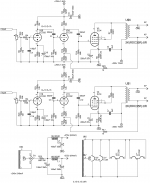
OK here is the schematic (hope you can see it)it is not mine but courtesy of sm lab.
However consider that I had to modify the power supply because I had two transformer available in house one for the HV and the second one usable as said for the heaters. All the rest is the same apart....
yes I have to confess that because of money I could not efforts to buy decent TU so I give a try with two toroid transformers I had in house obviously connected by using and inductor in parallel and a condenser in series in order to avoid saturation. Now you know all the story and blame me if you wish but it works and works well (for me). Don't forget that this was an exercise for me I must also say that I am the first to be surprised by the results.
Attachments
Ok this is a single ended amp but you need yo use a higher gain tube
like a 12AT7 or even a 6922 with a CCS. You don't have enough gain and I'm not sure why you connected the global NFB to the second stage?
like a 12AT7 or even a 6922 with a CCS. You don't have enough gain and I'm not sure why you connected the global NFB to the second stage?
Wouldn't a valve change i.e. replace the 12AU7 with one you propose require further adjustment to the schema? As said I am new to the business therefore not much capable in re design stages while the guy that made it is very skilled. Ref why the feedback goes on the second stage not sure but again the guy that made it must have his reasons
I could increase the gain reducing the feed back but in that case distortion would be higher?
I forget to mention that at moment the EL34 are connected in pentode mode not in triode as per schema
I could increase the gain reducing the feed back but in that case distortion would be higher?
I forget to mention that at moment the EL34 are connected in pentode mode not in triode as per schema
I give a try with two toroid transformers I had in house obviously connected by using and inductor in parallel and a condenser in series in order to avoid saturation.
Do you mean like this? What is the spec for the toroid? And what are the values for the coupling capacitor and inductor?

Last edited:
Yes just I did connect the capacitor ends between the output of the inductor and the transformer not between the output of the inductor and the tube as per yours (just move it a bit on the right side -))
Value are 20H for the inductor which I believe is to reduce noise and 4.7uF for the capacitor
Spec for the transformer is 220/12v 100VA for an estimated output load of 8 Homs
This is also from an other guy more skilled than me that help
Value are 20H for the inductor which I believe is to reduce noise and 4.7uF for the capacitor
Spec for the transformer is 220/12v 100VA for an estimated output load of 8 Homs
This is also from an other guy more skilled than me that help
Yes just I did connect the capacitor ends between the output of the inductor and the transformer not between the output of the inductor and the tube as per yours (just move it a bit on the right side -))
Value are 20H for the inductor which I believe is to reduce noise and 4.7uF for the capacitor
Spec for the transformer is 220/12v 100VA for an estimated output load of 8 Homs
This is also from an other guy more skilled than me that help
Yup, I made a stupid mistake drawing it up, I corrected it now... Actually, nothing wrong with the way you did it, in fact, it is commonly referred to as the parafeed or parallel-feed connection. Is the 4.7uF non-polarized? What happens when you remove the negative feedback (1k), does the amp still oscillate at full volume? Be careful, it may get very loud.🙂
If they are in pentode they are very easy to drive
You could move the NFB loop to the first tube. I don't think that basic design is set in stone and being you have instability in spite of so much NFB,going to the input tube may just solve some or all of your issues.
You could move the NFB loop to the first tube. I don't think that basic design is set in stone and being you have instability in spite of so much NFB,going to the input tube may just solve some or all of your issues.
Jazbo
Why do they feed the global nfb to the driver and not the voltage amp in the beginning?
May be just one less stage to deal with, so a bit more stable. I suspect the oscillation at full volume might be due to the non-spec toroid OPT...
I am out of country for work now and I cannot make any test I was just thinking about the problems I have with ampli at home and trying with your help to make a plan for when I go back to solve those problems
When I left the configuration was as said but the 4.7uF polypropylene jentzen (bloody expensive!!) is on order at moment an electrolytic 220uf is in place (this could also be causing some trouble?)
When I remove the NFB of course I get higher volume but to be honest I only tried that in early stage and I did not pay attention to this specific problem. But I shall try again when I can
And yes I can try to move the NFB loop to the first stage and see if it helps again when I can. Regarding the NFB I believe from what I experience that in such design it is necessary. If you remove it distortion increase to much (you can ear that) beside the EL34 without NFB at max output is rated 10%.Also it should increase the bandwidth. This may be not necessary if you use a Tamura TU but in my specific case a little help is welcome
What if I convert the AC for the ecc82 in DC? Would this help regarding the hum I can do that with a diode bridge and a condenser..
The coupling capacitor should really be non-polarized, so it has to be replaced eventually. The no feedback test is just to verify that the amplifier is perfectly stable without feedback - it should be.
To lower the hum, I think you can lower the 26V supply to 24V with some resistors, to me that's less important, first, you should make sure the amplifier is completely stable at full output, even if you are not likely to listen to music at that level.
To lower the hum, I think you can lower the 26V supply to 24V with some resistors, to me that's less important, first, you should make sure the amplifier is completely stable at full output, even if you are not likely to listen to music at that level.
ok guys here my action plan
1 fit the high quality condenser instead of the present electrolytic and see if better
2 remove NFB and see if instability disappear. In that case reduce NFB till is ok
3 in case try to move NFB to the first stage and see if help
This is in ref.to the instability (did I forget anything?)
In regards to the Hum I believe there is not so much to do other than try to have the best possible wiring and may be convert to DC at least the pre stage?(did I forget anything?)
In any case thank you all for the help great comunity
- Status
- Not open for further replies.
- Home
- Amplifiers
- Tubes / Valves
- Little help for a newbie?