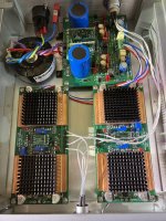
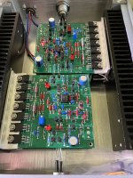
@baggerbole could you please tell me where the find build plan and BOM for CFA3Hi starcat, do you have more information about the CFA3. May be a link or an instruction guide?
Best
Bernd
There is no build plan. You populate the PCB by looking at the silkscreen and cross-checking with the schematic. I have a BOM but it's probably out of date by now.@baggerbole could you please tell me where the find build plan and BOM for CFA3
Jhofland recently designed for me a push pull diamond buffer output stage headphone amplifier with an opamp input stage in a nested feedback composite amp. It has direct coupled output and runs Class A for the first 50mw and can produce up to 1W into 32ohms (Class AB).
Here’s the schematic for the output stage. I’m using 2N5551 and 2N5401 models but actual outputs are SOT223 FT953/853. A green LED is used to control the CCS:

Here is the schematic showing the diamond buffer in a nested loop composite amp with an opamp providing 12dB gain, and a small circuit to enable turning on negative rail when the positive one is turned on with the volume pot click switch:

Here’s the bottom side with through hole parts - very similar to the Pocket Class A amp but with an SOIC8 opamp (here I am using basic NE5532 but plan to swap to OPA1642 later):

Here’s the top side with all the SMT components:

And here it is undergoing testing with two 9v batteries for +/-9v rails. It’s currently running a bit hot at 70mA bias current. I was lucky and it worked the first time without issue:

Based on success here I stuffed it into a mint tin:

Some silicone thermal pads had to be added to help sink the Class A heat to the lid. The bias was designed for 40mA but ended being closer to 70mA in practice (that is just LTspice models being off). Some resistor setpoints will need to be adjusted to trim this in a future build. A quick check with Oscope revealed a small 7MHz oscillation which was easily fixed with a 0.1uF and 15ohm to 47ohm resistor snubber on the output. Most high speed Class AB output stages have this at the output:

Anyhow, it sounded fantastic! Very detailed, clear, and superb dynamics. Did I mentioned the slamming bass? Anyhow, I liked it so much I adapted it to a desktop amp with a wall plug AC/DC converter PSU for +/-15v rails going through a CMC filter (salvaged from a PSU from a phono preamp project) followed by an LT linear regulator for +/-9v power with low noise. I used silicone RTV to bind a small heatsink on top of the outputs. Then installed the whole thing into an old chassis I had lying around for the last 6 years. I tried using a DIY light pipe indicator but that didn’t work too well since LED was side emitting. So ended up using LED powered by PSU which just shows standby only:


Here’s the snubber mod on the output:

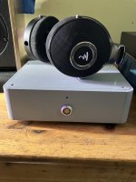
Here is is buttoned up:

Drives HE400i (32ohms and low sensitivity) very very well. Anyhow, I am listening and it’s one of the best headphone amps I have heard. Will measure it after I have a chance to do listening at extended periods. But predictions say 0.0007% THD at 4mW into 32ohms (typical power I use for most casual listening) and dominant second harmonic distortion:

I liked the desktop Diamond Buffer HPA so much I asked Jhofland to do a special layout with large TO126 through hole outputs and space for a large input cap for cap rolling. There’s enough room for a 4.7uF 400v MKP cap (optional) but one can use a small Wima 3.3uF boxcap if desired. I often use Silmic II 10uF 35v for inputs.
Here’s the schematic for the output stage. I’m using 2N5551 and 2N5401 models but actual outputs are SOT223 FT953/853. A green LED is used to control the CCS:
Here is the schematic showing the diamond buffer in a nested loop composite amp with an opamp providing 12dB gain, and a small circuit to enable turning on negative rail when the positive one is turned on with the volume pot click switch:
Here’s the bottom side with through hole parts - very similar to the Pocket Class A amp but with an SOIC8 opamp (here I am using basic NE5532 but plan to swap to OPA1642 later):
Here’s the top side with all the SMT components:
And here it is undergoing testing with two 9v batteries for +/-9v rails. It’s currently running a bit hot at 70mA bias current. I was lucky and it worked the first time without issue:
Based on success here I stuffed it into a mint tin:
Some silicone thermal pads had to be added to help sink the Class A heat to the lid. The bias was designed for 40mA but ended being closer to 70mA in practice (that is just LTspice models being off). Some resistor setpoints will need to be adjusted to trim this in a future build. A quick check with Oscope revealed a small 7MHz oscillation which was easily fixed with a 0.1uF and 15ohm to 47ohm resistor snubber on the output. Most high speed Class AB output stages have this at the output:
Anyhow, it sounded fantastic! Very detailed, clear, and superb dynamics. Did I mentioned the slamming bass? Anyhow, I liked it so much I adapted it to a desktop amp with a wall plug AC/DC converter PSU for +/-15v rails going through a CMC filter (salvaged from a PSU from a phono preamp project) followed by an LT linear regulator for +/-9v power with low noise. I used silicone RTV to bind a small heatsink on top of the outputs. Then installed the whole thing into an old chassis I had lying around for the last 6 years. I tried using a DIY light pipe indicator but that didn’t work too well since LED was side emitting. So ended up using LED powered by PSU which just shows standby only:
Here’s the snubber mod on the output:
Here is is buttoned up:
Drives HE400i (32ohms and low sensitivity) very very well. Anyhow, I am listening and it’s one of the best headphone amps I have heard. Will measure it after I have a chance to do listening at extended periods. But predictions say 0.0007% THD at 4mW into 32ohms (typical power I use for most casual listening) and dominant second harmonic distortion:
I liked the desktop Diamond Buffer HPA so much I asked Jhofland to do a special layout with large TO126 through hole outputs and space for a large input cap for cap rolling. There’s enough room for a 4.7uF 400v MKP cap (optional) but one can use a small Wima 3.3uF boxcap if desired. I often use Silmic II 10uF 35v for inputs.
Good afternoon, xrk971. Can I repeat your project?
Very intrigued. I want to use it with headphones Sivga Audio P-II
If possible, I would like to ask you something.
1. I see you used a dual transistor instead of two single ones 2N5401. What is it called?
2. Is there anything else that I need to finalize in the scheme? In addition to adding an RC lock scheme.
The dual parts are DMMTxxxx. I use DMMT5401-7 and DMMT5551-7 parts. The SOT-223 power transistors are FZT953 and FZT853 - nice units capable of a lot of drive. The complete BOM is here.
I recently made measurements of this same amp, but as mounted in an Altoids tin and two 9v rechargeable batteries. The performance was very good - nice SE Class A like harmonic distortion profile.
Here is 50mW into 33ohms, about 0.0018% THD. Max power was 373mW before clipping, but nice harmonic profile up to 270mW.

The 60/120Hz noise peaks are just ambient lab noise picked up through the air as this was battery powered.
Here is 273mW into 33ohms:

The schematic as shown above works (albeit runs pretty hot circa 70mA bias current in practice when LTspice predicted 40mA). The circuit just needs an output snubber to resist oscillation at 7MHz. So with the addition of 10ohm (8.2ohm to 47ohm try various values with O-scope to check oscillation) and 100nF to ground on the outputs, it should be good to go. Member @lineup suggested a resistor in series on the output before the headphone load to ensure stability under a capacitive load. I suppose one could put 10ohm and 15uH air coil inductor (parallel) as a Thiele network at the output to ensure stability.
On the pocket version, I used 8.2ohms and on desktop version 47ohms seems to work for the output snubber.
If you really want to make it great, add a DC output protection relay. I would use a solid state relay (SSR) scheme with a 2 second turn-on delay and instant-off at power off feature to prevent thump and protect from headphones from DC in case one rail collapses before the other. I ran out of room to implement the SSR on this small board though. You may want to tweak the bias current by increasing the 2.2R emitter resistors to 4.7R and this will let it run cooler without really affecting performance too much. But if you have good heatsinking, it’s fine as is. 🙂
A friend of mine tested this amp with his HiFiMan (flagship) Susvara headphones and said there was enough power to drive two of them in parallel to very loud distortion free levels. He really enjoyed the amp and said it is just as good as his much larger and much more expensive amps. This amp should drive Sivga P-II’s well as that matches the 33ohm test load. Also, my own test with 32ohm HE-400i’s indicates that it will work well.

I recently made measurements of this same amp, but as mounted in an Altoids tin and two 9v rechargeable batteries. The performance was very good - nice SE Class A like harmonic distortion profile.
Here is 50mW into 33ohms, about 0.0018% THD. Max power was 373mW before clipping, but nice harmonic profile up to 270mW.
The 60/120Hz noise peaks are just ambient lab noise picked up through the air as this was battery powered.
Here is 273mW into 33ohms:
The schematic as shown above works (albeit runs pretty hot circa 70mA bias current in practice when LTspice predicted 40mA). The circuit just needs an output snubber to resist oscillation at 7MHz. So with the addition of 10ohm (8.2ohm to 47ohm try various values with O-scope to check oscillation) and 100nF to ground on the outputs, it should be good to go. Member @lineup suggested a resistor in series on the output before the headphone load to ensure stability under a capacitive load. I suppose one could put 10ohm and 15uH air coil inductor (parallel) as a Thiele network at the output to ensure stability.
On the pocket version, I used 8.2ohms and on desktop version 47ohms seems to work for the output snubber.
If you really want to make it great, add a DC output protection relay. I would use a solid state relay (SSR) scheme with a 2 second turn-on delay and instant-off at power off feature to prevent thump and protect from headphones from DC in case one rail collapses before the other. I ran out of room to implement the SSR on this small board though. You may want to tweak the bias current by increasing the 2.2R emitter resistors to 4.7R and this will let it run cooler without really affecting performance too much. But if you have good heatsinking, it’s fine as is. 🙂
A friend of mine tested this amp with his HiFiMan (flagship) Susvara headphones and said there was enough power to drive two of them in parallel to very loud distortion free levels. He really enjoyed the amp and said it is just as good as his much larger and much more expensive amps. This amp should drive Sivga P-II’s well as that matches the 33ohm test load. Also, my own test with 32ohm HE-400i’s indicates that it will work well.
Last edited:
Do you think you could send me information on this as well? I am new to the site and so cannot pm yetPM'ed already 🙂 Happy building.
Have about a dozen of headphone amps, but only 3 made it into my main headphones bench: ACP+, Whammy and Lehmann.
Aegis tube headphone amp, beats all the other solid state one I ever built… Big, heavy, expensive, but so musical.
sB
sB
Thanks for mentioning the preamp @ElArte! Yeah, it has turned out to be a great headphone amp. Need to finish that PCB.
For a tube headphone amp this is my endgame amp. I got lazy and went with a Schiit Mjolir3 , it is everything I wanted in a solid state amp and frankly it would have costed me more to build it myself. Though two other solid state amps I have built worth mentioning Alex cp’s Omicron and Bonsai’s X-Altra Hpa-1 both are smd and very approachable designs for learning smd soldering, and both sound excellent.Aegis tube headphone amp, beats all the other solid state one I ever built… Big, heavy, expensive, but so musical.
sB
Bill
This is my first post on this forum.
I want to build a DIY amplifier for the first time.
I've seen many posts related to the Dynalo amplifier, but I can only find the circuit diagram designed in 2014, attached in the file (kg dynalo balanced super symmetry).
I've tried to replicate the schematic, but for some components, I have no idea which ones can be used.
For example, for the op27, I can only find many special part numbers on Mouser, and I have no idea which one is correct to use.
Also, the op27 has 8 pins, so it should have V+ and V- pins, which are not drawn in the previous circuit diagram.
Considering I have no experience in building any DIY projects by myself, I don't think I can complete the entire task on my own. (Also need to convert to PCB layout...)
However, it seems that some Gerber files provided by the author or others on the Head-Fi and Head-Case forums are all dead.
Could anyone provide the Gerber files and BOM for the Dynalo? Many thanks.
Attachments
I agree it can be difficult (if not impossible) to find the documentation and files for the stuff on Head-Fi and Head-Case. They have a habit of not attaching the files to the forum posts, and their links tend to go bad after a while. That said, @kevin gilmore shares his files on Google, see here: https://www.head-fi.org/threads/stax-mafia-google-shares-updated-links.970827/#post-17852660
That seems off. The Susvara really needs a very powerful amp, such as a loudspaker ampflifier. If the amplifier really drives a Susvara properly (or even two in parallel), it will have to output a lot more power.Max power was 373mW before clipping, but nice harmonic profile up to 270mW.
....
A friend of mine tested this amp with his HiFiMan (flagship) Susvara headphones and said there was enough power to drive two of them in parallel to very loud distortion free levels.
What load impedance did you use when you measured the 0.37 W max. power?
- Home
- Amplifiers
- Headphone Systems
- List of best DIY Headphone Amplifiers


