Anatomy of a BLAT.
No not that one. This one - Bomac Liquid Audio Technology. It started out as just the BLA, but applied to a 2.1 speaker system it resolves to Bla, Bla, Bla. Not good. So added the “T” and was quickly advised by JB (lehmanhill) that I had moved from the shop to the kitchen.
I have several PCs with liquid cooling and mostly out of curiosity wanted to apply that method to audio. Purchased two of these on a whim and collected the necessary parts from the stash. No way to drill into the coolers so a standoff plate was built.
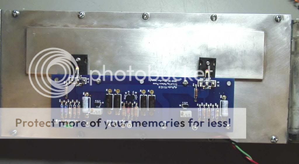
Located the mounting hole by spreading compound on the chip which was soldered to the PCB with standoffs attached.


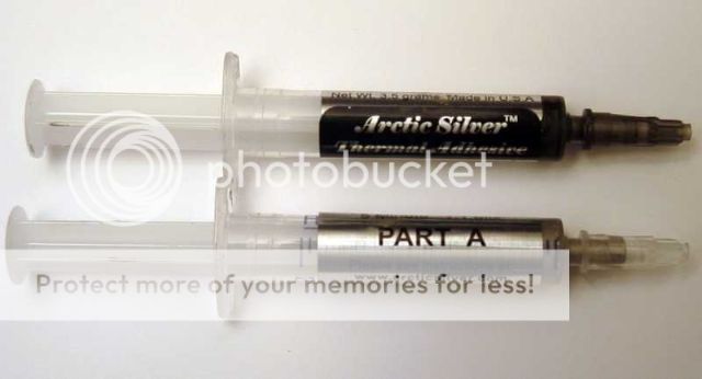
The simplest, though not most efficient way to combine the plate and the cooler was double sided heat transfer tape. They were clamped together overnight for a solid set. If I do another one I'll make some sort of bracket that will allow the use of paste instead of thermal tape.


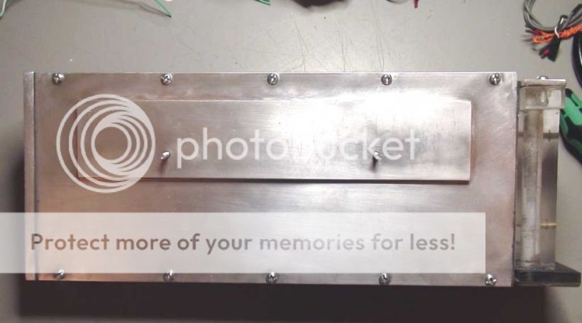
Mounted amp module to cooler and cut tubing links.


No not that one. This one - Bomac Liquid Audio Technology. It started out as just the BLA, but applied to a 2.1 speaker system it resolves to Bla, Bla, Bla. Not good. So added the “T” and was quickly advised by JB (lehmanhill) that I had moved from the shop to the kitchen.
I have several PCs with liquid cooling and mostly out of curiosity wanted to apply that method to audio. Purchased two of these on a whim and collected the necessary parts from the stash. No way to drill into the coolers so a standoff plate was built.
Located the mounting hole by spreading compound on the chip which was soldered to the PCB with standoffs attached.
The simplest, though not most efficient way to combine the plate and the cooler was double sided heat transfer tape. They were clamped together overnight for a solid set. If I do another one I'll make some sort of bracket that will allow the use of paste instead of thermal tape.
Mounted amp module to cooler and cut tubing links.
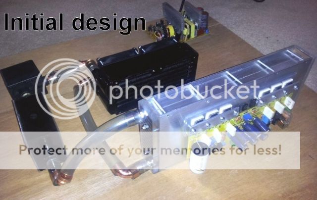
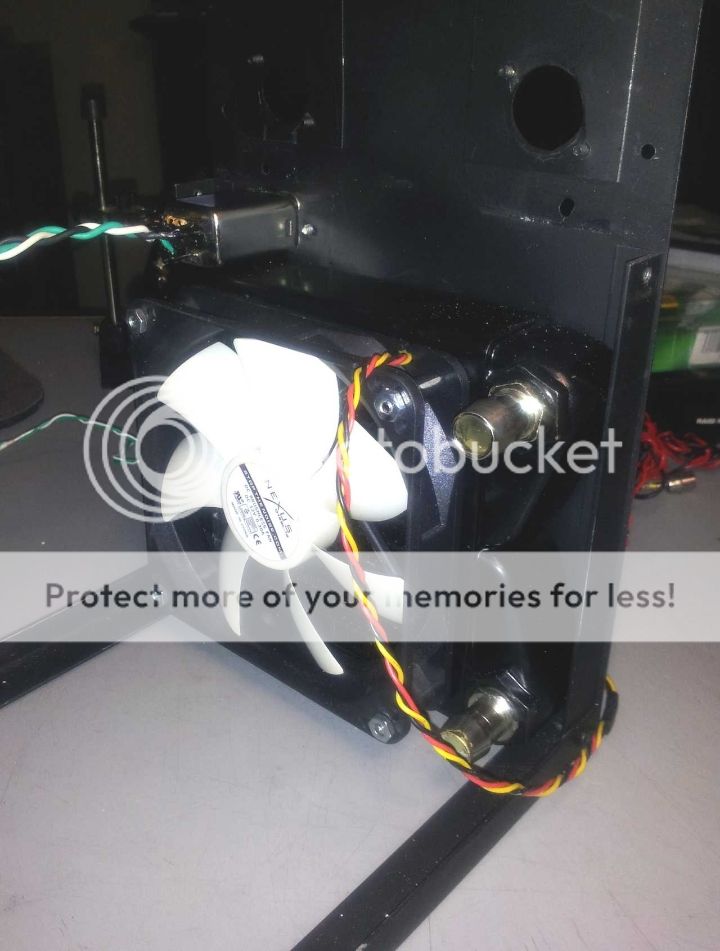
]First shot was built on plywood frame. The cooling elements were all standard 80 mm format.


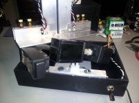
Fill port/air release worked great but I didn’t like having the liquid that close to the amps.


Here the system is making cool music with no leaks and a stable temp just above ambient.

Fill port/air release worked great but I didn’t like having the liquid that close to the amps.
Here the system is making cool music with no leaks and a stable temp just above ambient.
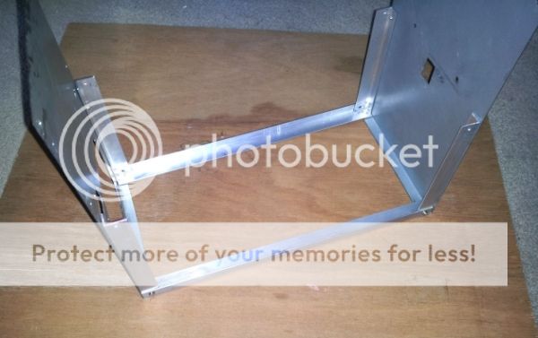
Second attampt was centered around the idea of keeping the liquid below the amp. Cobbled up another woden frame and placed my chin firmly on my palm and began to ponder.


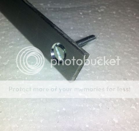
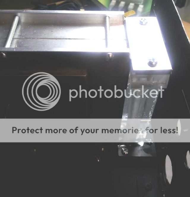
Started fabrication of base for cooling system with 1/8” x 2” aluminum angle from the local hardware store. Transformer brackets are from ¼’ x 3’ angle.


Attached 1/16” corner braces with two part epoxy for both stability and squareness.


Started fabrication of base for cooling system with 1/8” x 2” aluminum angle from the local hardware store. Transformer brackets are from ¼’ x 3’ angle.
Attached 1/16” corner braces with two part epoxy for both stability and squareness.
Attachments
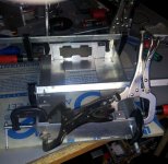

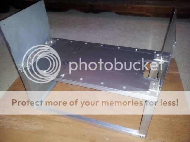
Photo of lap/inset construction.


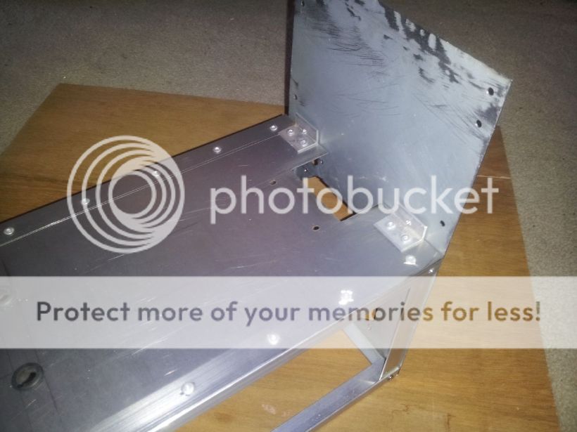
Underside with support/feet and a touch of Bondo for the oopses from hand cutting.

Holes for bottom supports are countersunk for flathead screws.


Corner reliefs for wire paths on transformer bracket.


Looks like it’s going to work so now on to the reservoir.
Underside with support/feet and a touch of Bondo for the oopses from hand cutting.
Holes for bottom supports are countersunk for flathead screws.
Corner reliefs for wire paths on transformer bracket.
Looks like it’s going to work so now on to the reservoir.
Initially hoped to do a combo pump/reservoir with a fish tank AC powered unit. But it was too big for the cooling box. As luck would have it, the seven year old pump in my main PC lost a bearing during this time so it wasn’t a total waste.

Right method but still to awkward for installation in the BLAT.


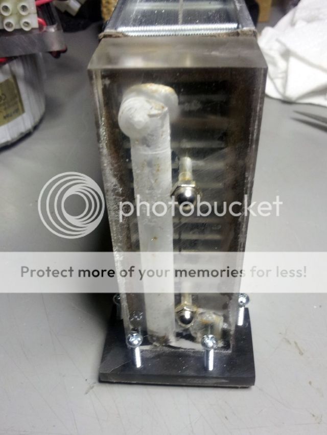
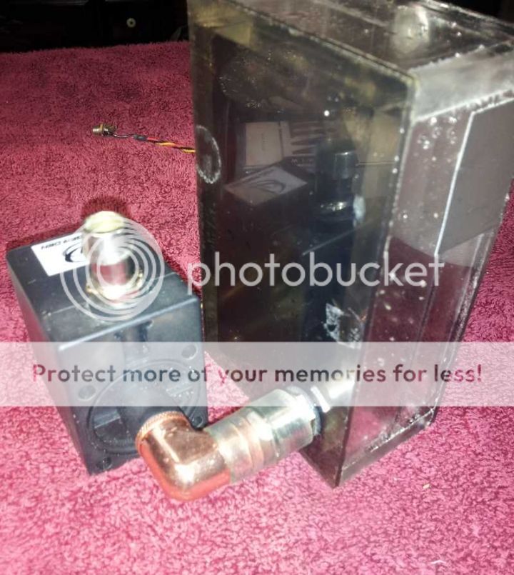
Gave up on the combo unit and built a res I knew would fit.

Shows outline of inlet deflection plate and square outlet suction tube.

Here are some leak test pics. Problems can be masked when the system is active so an overnight non-powered proof was done.


Right method but still to awkward for installation in the BLAT.
Gave up on the combo unit and built a res I knew would fit.
Shows outline of inlet deflection plate and square outlet suction tube.
Here are some leak test pics. Problems can be masked when the system is active so an overnight non-powered proof was done.
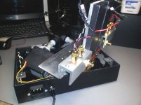
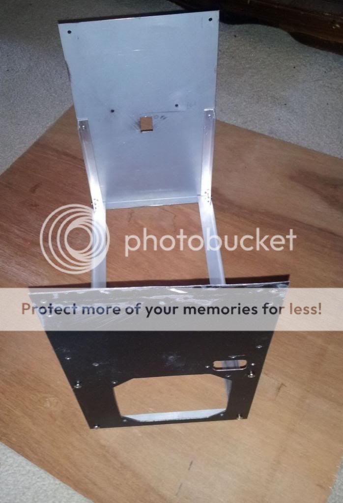
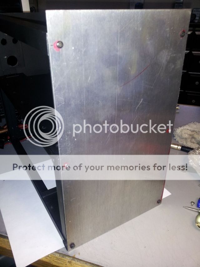
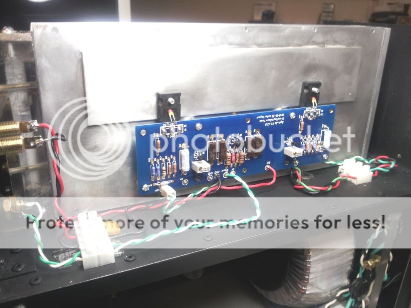
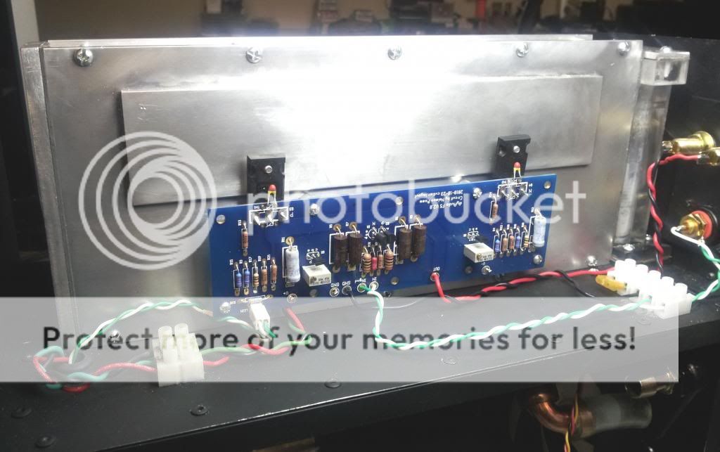
Oh, I forgot about the signal. With my chin still firmly mounted on my palm (visualize “The Thinker”) the following developed. There wasn't enough room to mount the posts in the standard position without inteference with the cooling tubes. A 90 degree flip did the trick.


More corner removal to prevent the possibility of a short from insulation damage.

Looks like everything fits.


More corner removal to prevent the possibility of a short from insulation damage.
Looks like everything fits.
Wall wart DC socket for pump/fans, AC inlet with self-contained fuse and safety ground lug.

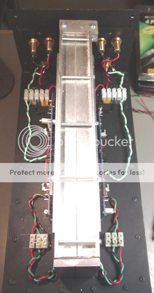
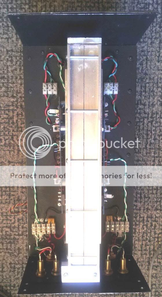
Putting it all together with wiring. Hoorraay!


Cut and tape together possible cover from postboard. It was then glued together and all the tape removed.


For the purpose of collecting some temperature data, I also made a standard cooling rig for comparison/discovery of efficiency.


Still have to decide where to place remote FE LEDs, or change to a lighted main switch.
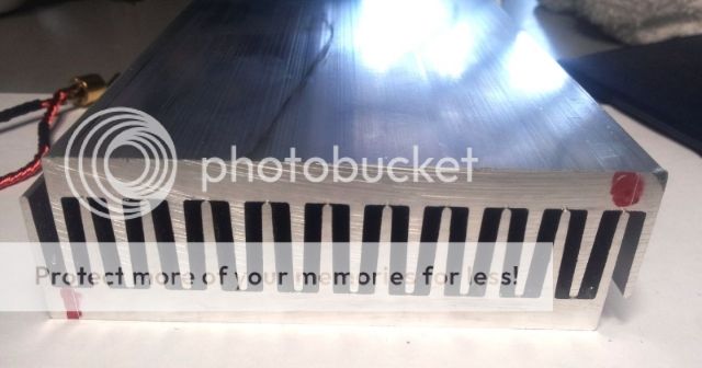
This is the smallest format - 40mm, but 70, 80, and 120 are available if your amp can heat your music room on an autumn afternoon.
There you have it. The anatomy of a BLAT. Great fun and a worthy challenge. Probably not where Dario thought his excellent design would end up, but I couldn't resist.
Cooling liquid is the same as what has been used in the PCs.
Putting it all together with wiring. Hoorraay!
Cut and tape together possible cover from postboard. It was then glued together and all the tape removed.
For the purpose of collecting some temperature data, I also made a standard cooling rig for comparison/discovery of efficiency.
Still have to decide where to place remote FE LEDs, or change to a lighted main switch.
This is the smallest format - 40mm, but 70, 80, and 120 are available if your amp can heat your music room on an autumn afternoon.
There you have it. The anatomy of a BLAT. Great fun and a worthy challenge. Probably not where Dario thought his excellent design would end up, but I couldn't resist.
Cooling liquid is the same as what has been used in the PCs.
Last edited:
Andrew, I got two answers to your question:
1. It's the same as the answer to the question "Why does a man climb a mountain?"
2. A three letter word that starts with "F" and ends with "N". You may or may not be familiar with the concept.😀
P.S. and maybe a little useful discovery.
1. It's the same as the answer to the question "Why does a man climb a mountain?"
2. A three letter word that starts with "F" and ends with "N". You may or may not be familiar with the concept.😀
P.S. and maybe a little useful discovery.
A coupe photos that give a better view of the cooling system.
The leak test thumbnail was mistakenly placed in earlier post.
The leak test thumbnail was mistakenly placed in earlier post.
Attachments


Last edited:
Final fill and leak test in progress. Reservoir cap will be screwed in after all visible air pockets are removed. Once sealed any remaining air (very tiny invisible bubbles) will collect at the top of the reservoir by displacement. The liquid is being drawn from the bottom of the chamber so no further air/liquid mixing will occur.
Attachments

Last edited:
This is a pictorial of the construction of the third version of a chassis incorporating liquid cooling for audio equipment – in this case power amps. It is humorously named the BLAT3 which stands for either Bomac Liquid Audio Technology or Bacon, lettuce, avocado and tomato – your choice. 😉

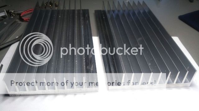
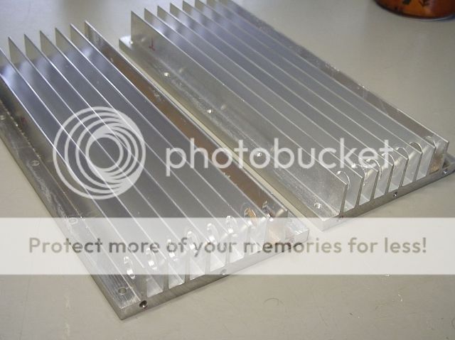
As previously posted, the second version captured the basics. The use of two pieces of standard aluminum heat-sink panels, from Heatsinks USA here in Michigan, eliminated the need for attaching fins via small c-channel strips with screws.
(There is a bit of jumping between cooler blocks here as I’m still finalizing the smaller/thicker piece.)
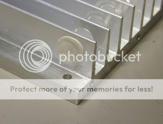
The third version uses a product with a thicker base that allows direct drilling of blind tapped holes for component mounting.
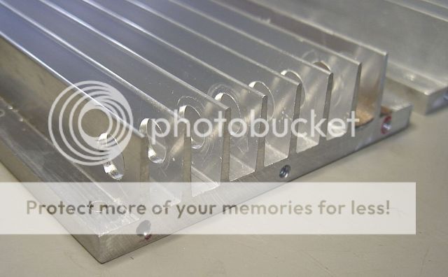
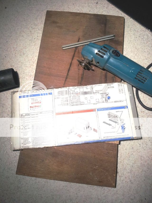
Layout marks for outer fin removal to establish final width.
Mark fins to be removed to create inlet and outlet paths.
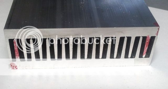
Metal was removed using a carbide tipped blade on a table saw.
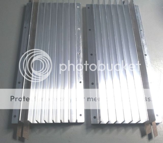
Here the halves have been drilled a tapped (one side) and placement of paper automotive gasket material to isolate I/O channels from main cooling segment - attached with GOOP Marine Adhesive.
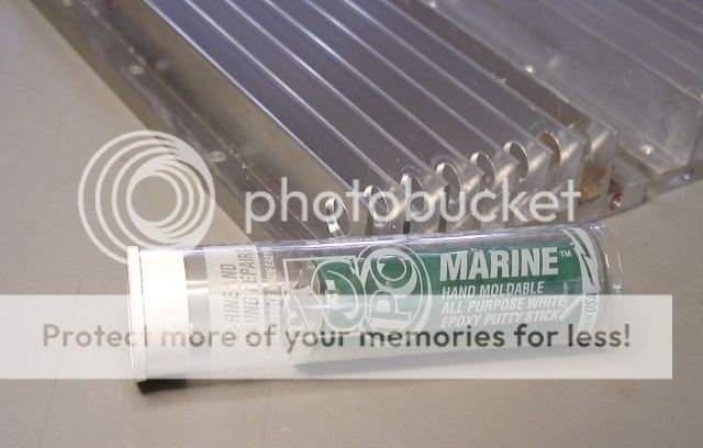
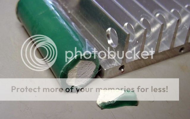
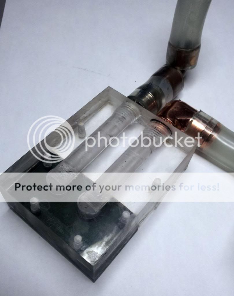
Full width flow holes are drilled. Marine Epoxy Putty is used to cap and divert alternating front to back circulation paths as needed. (Not completed on this unit) Various holes will be either plugged or added to create optimum flow pattern.
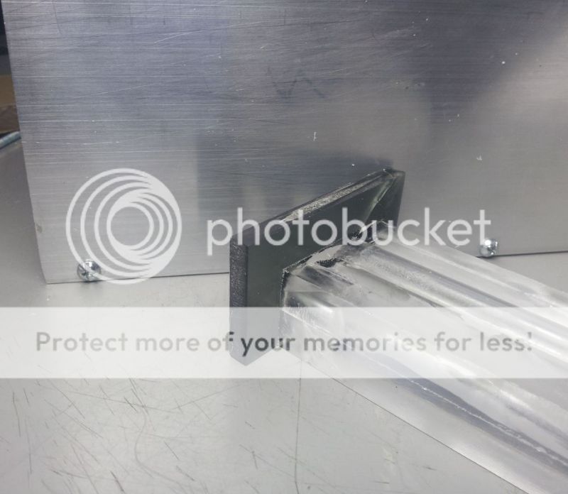
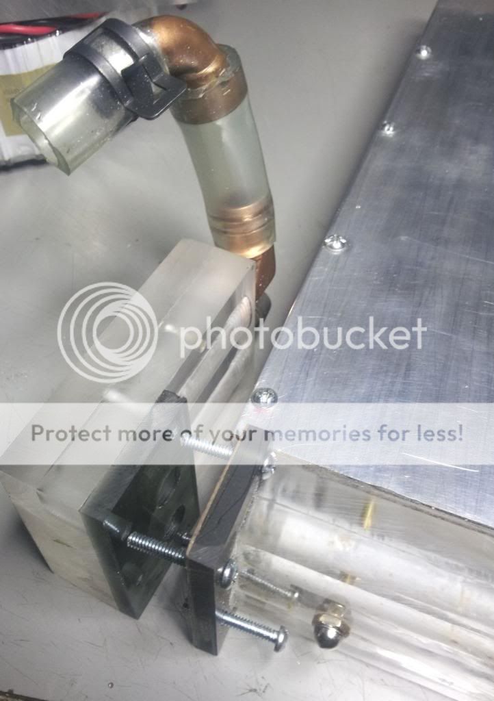
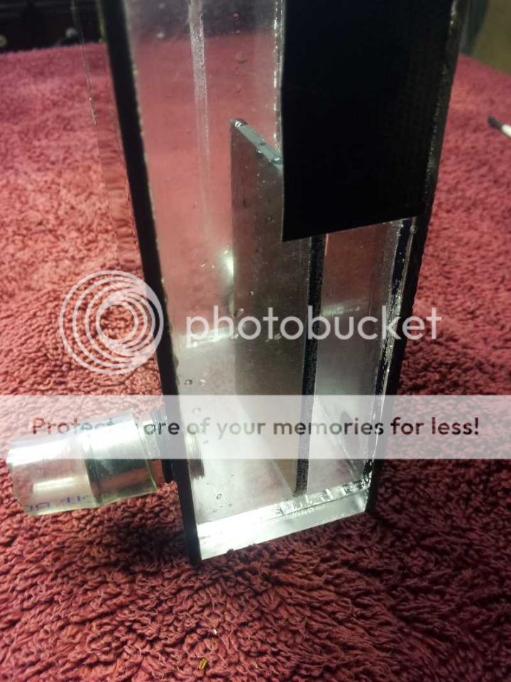
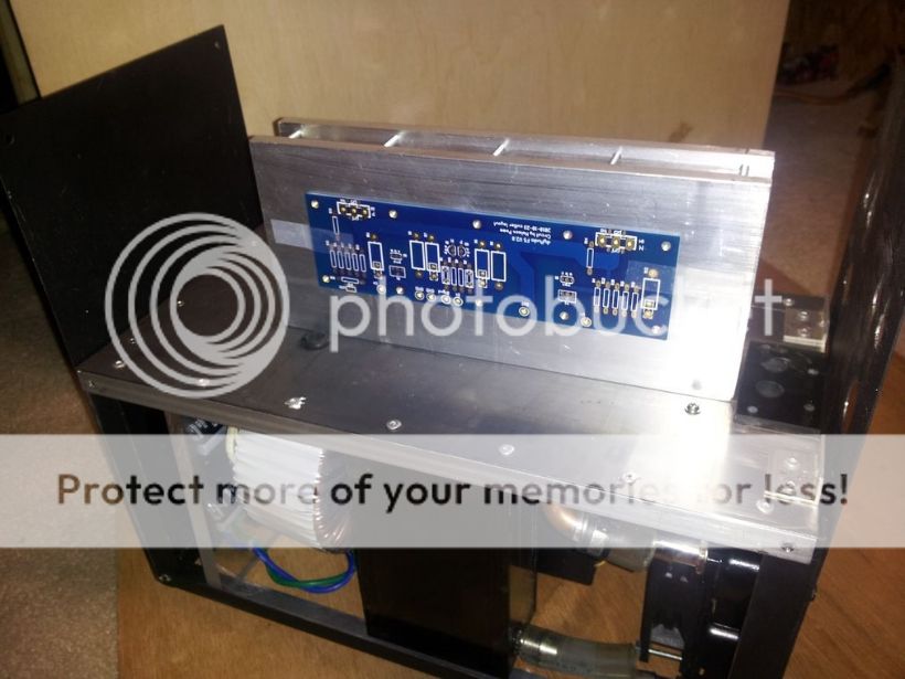
The major change in this third version is the elimination of several copper and plastic tubes by using a laminate of thick Plexiglas. Here is the construction before final drilling.
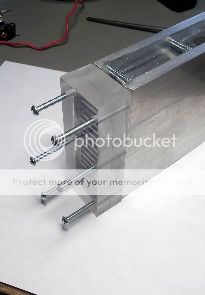
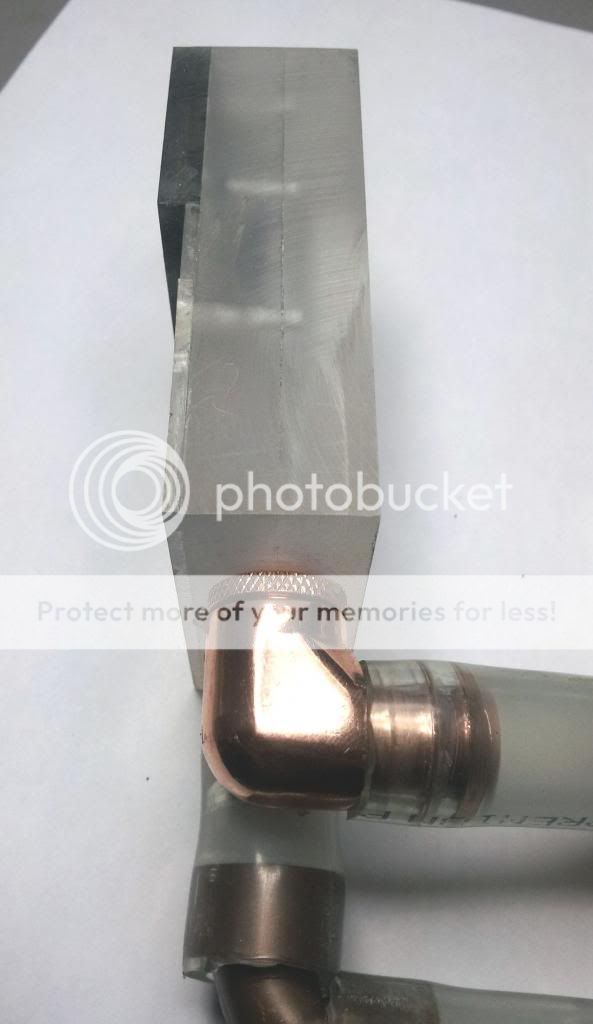
This is the current module with inlet (low) and outlet (high) passages with internal 90 degree turns.
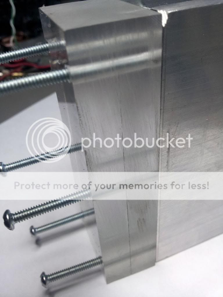
The bottom element consists of a paper gasket (not shown), a matching flange and another right angle turn drilled module.
Upper flow tube unit is attached with threaded rod anchored in the aluminum plate at the opposite end and secured with acorn nuts that prevent leakage. The original steele rods and nuts rusted quickly and were replaced with brass.
The lower unit is attached to the amp floor using 6-32 screws.
As previously posted, the second version captured the basics. The use of two pieces of standard aluminum heat-sink panels, from Heatsinks USA here in Michigan, eliminated the need for attaching fins via small c-channel strips with screws.
(There is a bit of jumping between cooler blocks here as I’m still finalizing the smaller/thicker piece.)
The third version uses a product with a thicker base that allows direct drilling of blind tapped holes for component mounting.
Layout marks for outer fin removal to establish final width.
Mark fins to be removed to create inlet and outlet paths.
Metal was removed using a carbide tipped blade on a table saw.
Here the halves have been drilled a tapped (one side) and placement of paper automotive gasket material to isolate I/O channels from main cooling segment - attached with GOOP Marine Adhesive.
Full width flow holes are drilled. Marine Epoxy Putty is used to cap and divert alternating front to back circulation paths as needed. (Not completed on this unit) Various holes will be either plugged or added to create optimum flow pattern.
The major change in this third version is the elimination of several copper and plastic tubes by using a laminate of thick Plexiglas. Here is the construction before final drilling.
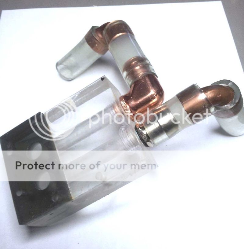
This is the current module with inlet (low) and outlet (high) passages with internal 90 degree turns.
The bottom element consists of a paper gasket (not shown), a matching flange and another right angle turn drilled module.
Upper flow tube unit is attached with threaded rod anchored in the aluminum plate at the opposite end and secured with acorn nuts that prevent leakage. The original steele rods and nuts rusted quickly and were replaced with brass.
The lower unit is attached to the amp floor using 6-32 screws.
Last edited:
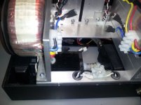
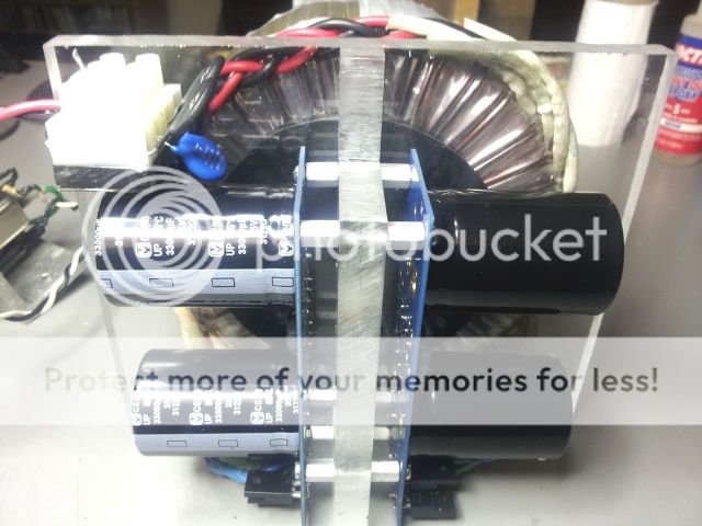
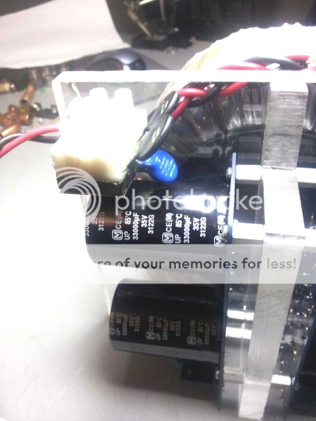
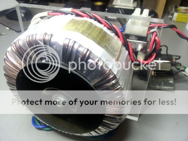
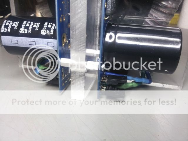
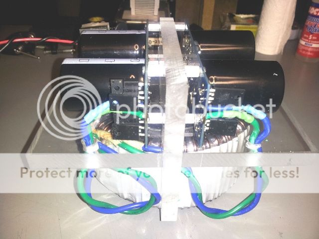
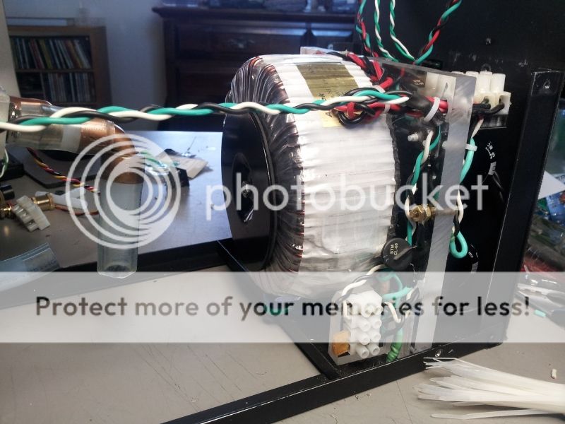
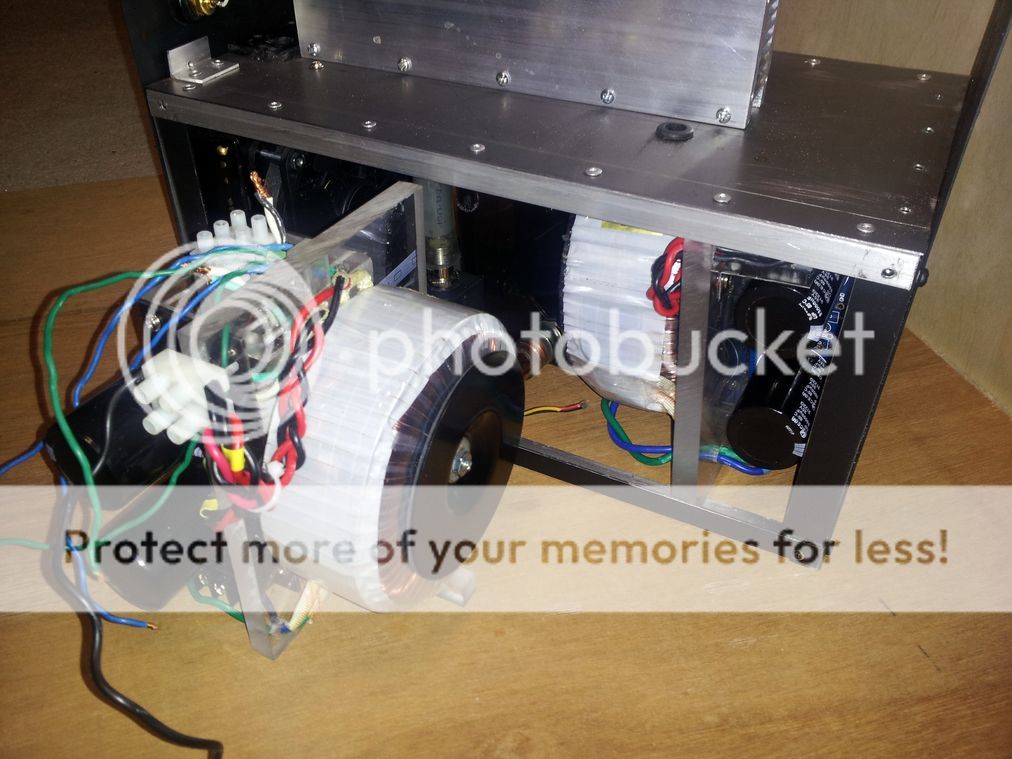
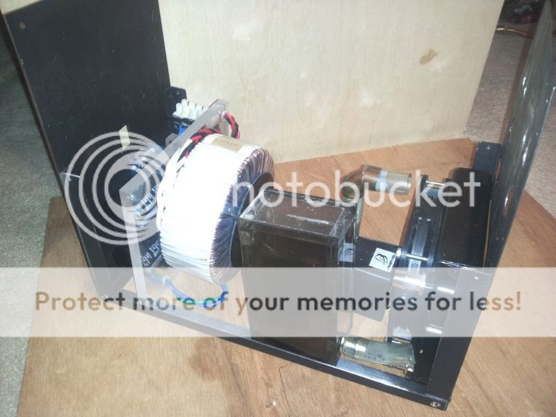
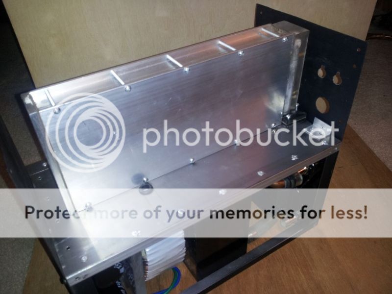
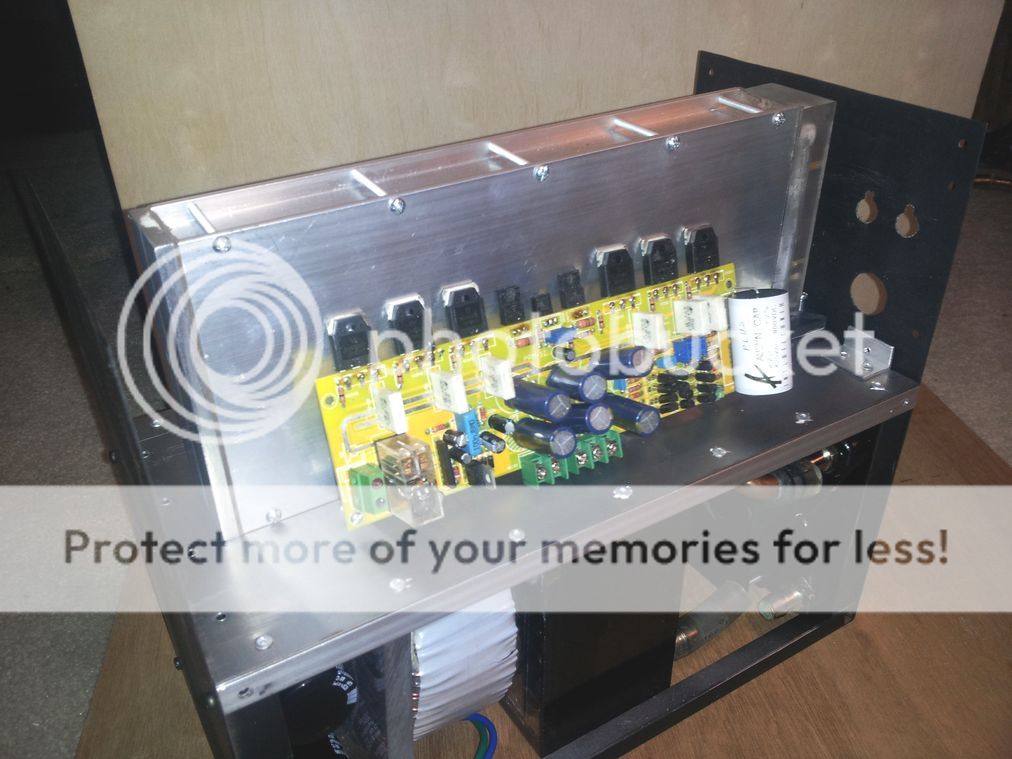
The chassis is designed to be modular - amp, power supply and cooler. Again, the use of thick Plexiglas aided in quick prototyping and adjustments. The base is a pair of Peter Daniels Universal PS boards populated with 33,000 uF caps and Fairchild Stealth 8A 600V rectifiers. That's an Antek 500 VA toroid.
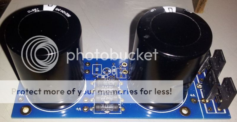
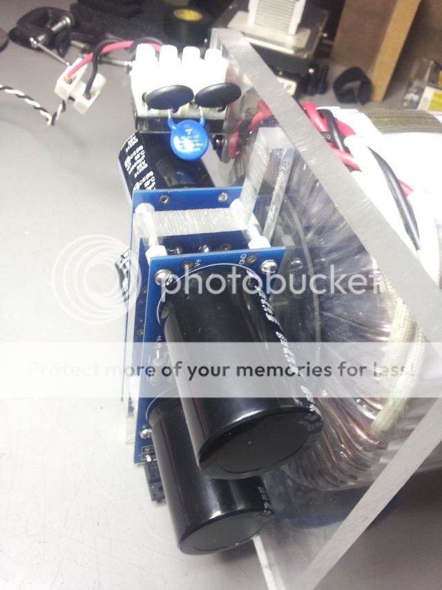
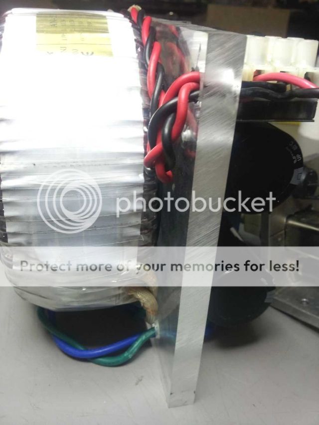
Plexiglas has the potential to collect static electricity. If screwing to frame isn't enough a braided copper strip may be added.
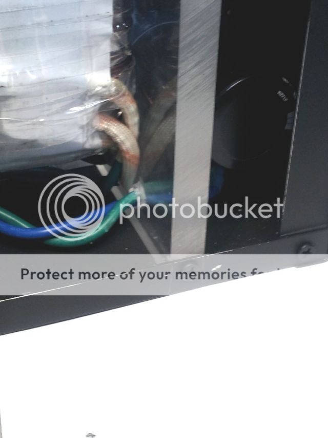
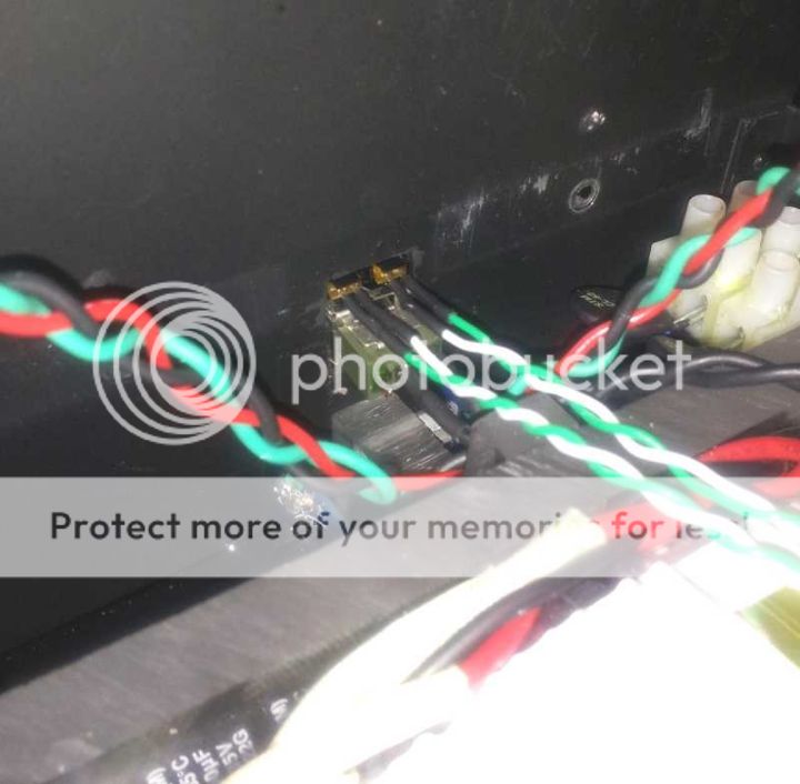
Green/white wires are leads for the LEDs built into the mains power switch.
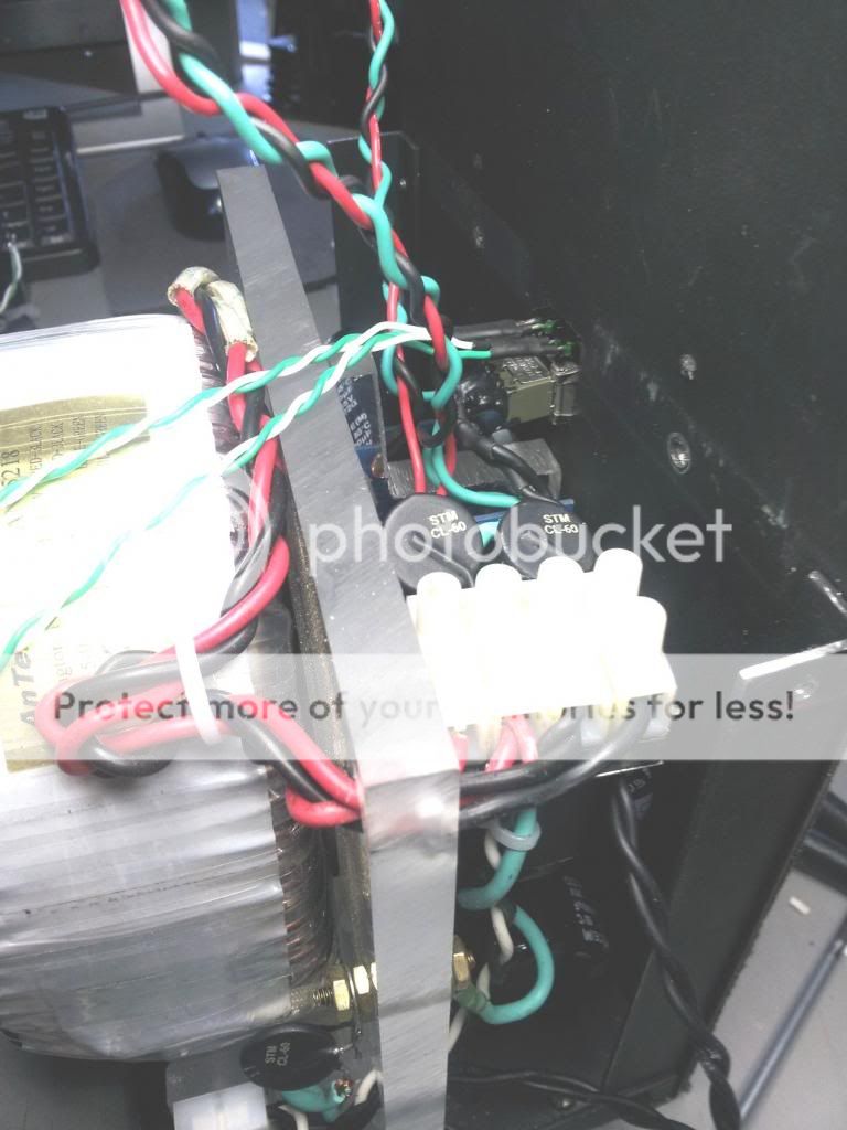
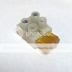
Since this entire project was one of those "Throw everything in a pile and remove what doesn't look like an amp 🙂" I found there wasn't enough room for a switch/fuse combo unit. I discovered the 12 position Euro style barrier strip spacing is a match for mini automotive fuses. Still have to get some 2A - 4A fuses but it worked out just fine.
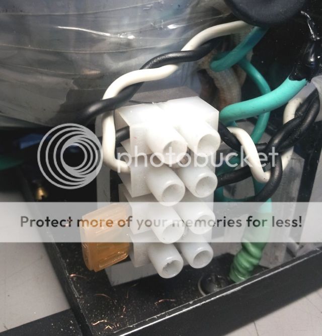
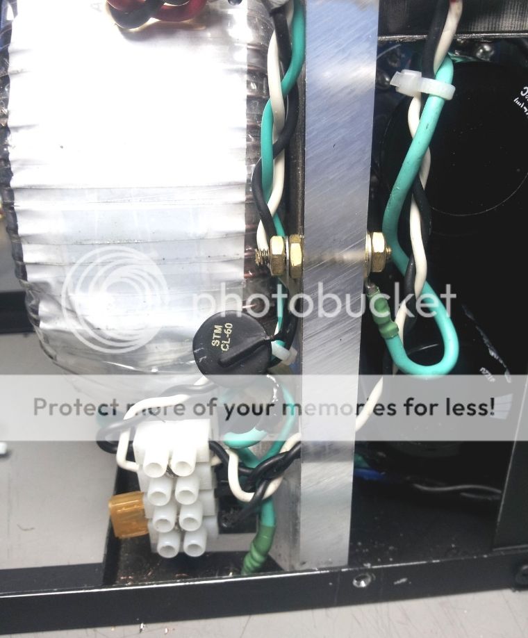
CL-60 from PS to chassis with brass pass-through bolt.
Green/black/white leads to AEC inlet at rear of chassis.
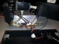
This is a similar unit for a pair of Honey Badger modules. The PS boards are my first DIY attempt completed with much appreciated help and direction from Daniel H. and 6L6.
Plexiglas has the potential to collect static electricity. If screwing to frame isn't enough a braided copper strip may be added.
Green/white wires are leads for the LEDs built into the mains power switch.
Since this entire project was one of those "Throw everything in a pile and remove what doesn't look like an amp 🙂" I found there wasn't enough room for a switch/fuse combo unit. I discovered the 12 position Euro style barrier strip spacing is a match for mini automotive fuses. Still have to get some 2A - 4A fuses but it worked out just fine.
CL-60 from PS to chassis with brass pass-through bolt.
Green/black/white leads to AEC inlet at rear of chassis.
This is a similar unit for a pair of Honey Badger modules. The PS boards are my first DIY attempt completed with much appreciated help and direction from Daniel H. and 6L6.
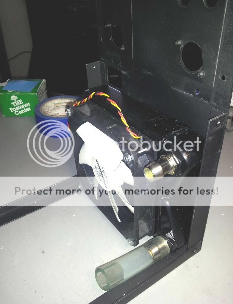
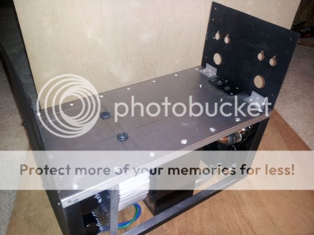
Finally found a use for some salvaged IBM server chassis parts. 😉
Rails are standard local hardware aluminum angle.
Switch, fan and mains inlet cut-outs.
Amp module floor riveted to intermediate rail supports. Added braces, cooler cut-out and rubber grommets for power leads.

Another scrap from an earlier project for the front.
*********************
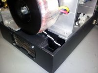
These are the active components of the cooling system. There are several super quiet fans available from PC outlets. This and the Yate Loon are among the best.
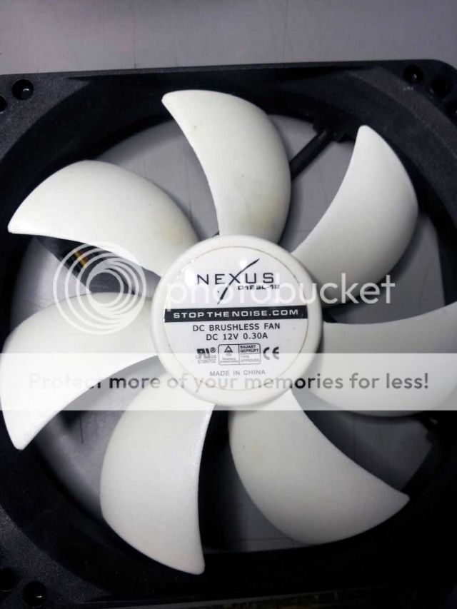
Fan is attached to a 120mm radiator. I didn't use additional vibration insulating pads as the fan will run at a derated voltage and should be very quiet.
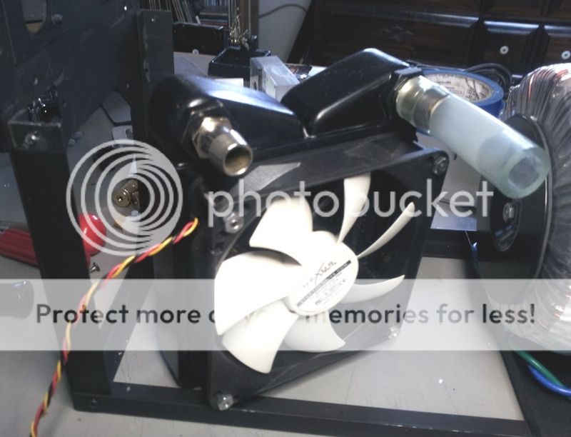
Radiator orientation has some effect on air pocket creation but a little twisting and rotating after final assembly moves them out.
Again, no gasket between radiator and chassis. Easy to add later if necessary.

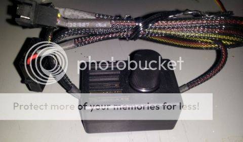
I purchased a discrete speed controller but will most likely incorporate internal trimmers after cooling efficiency tests.
**********
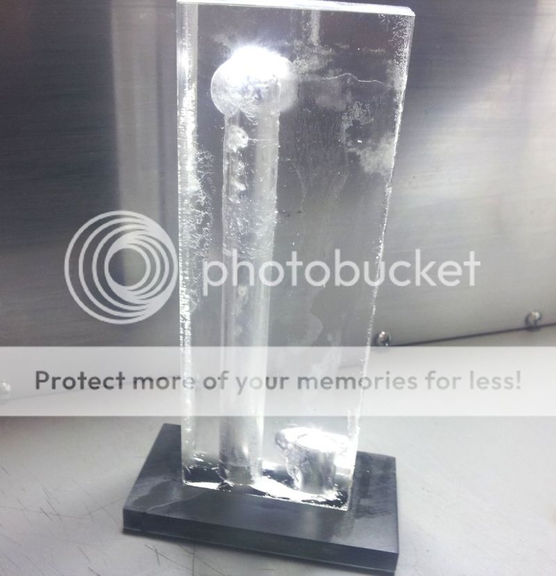
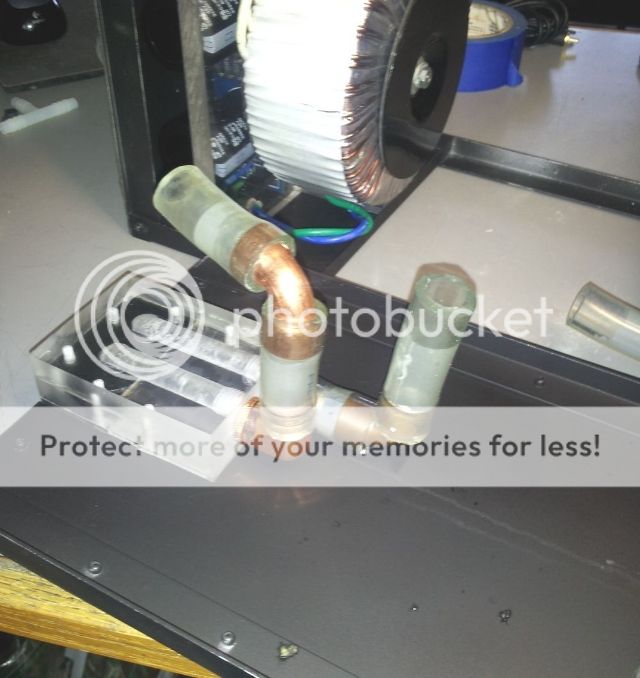
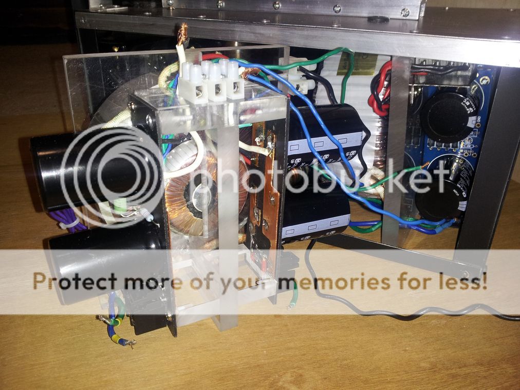
For the reservoir Plexiglas again comes to the rescue. Any size/shape can be made and the medium threads almost as cleanly as metal.
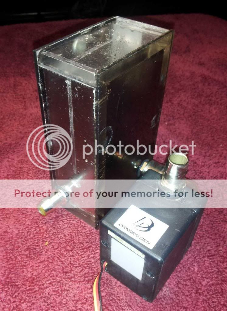
The copper fitting is called a "stub rotating 90" and allows for easy adjustment of placement, angle and connecting tube length.
The plugs are modified standard fittings.
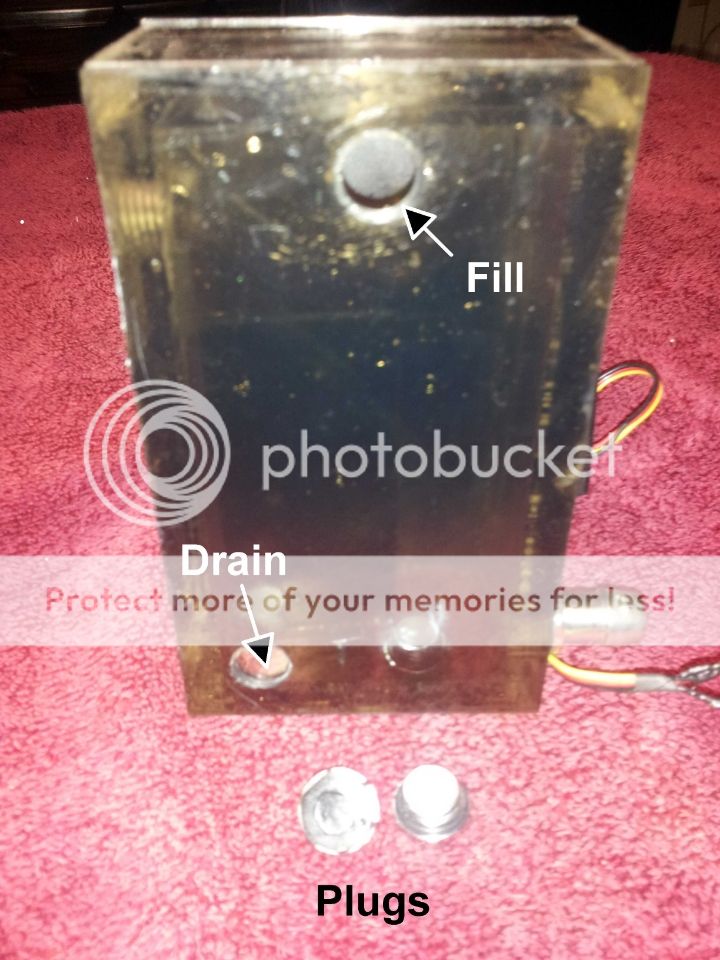
There is a diverter plate that enhances the potential for air bubbles to disperse to the top of the cooling fluid.
**********
Putting it all together!!!
With Honey Badger Clone
With F5 module.
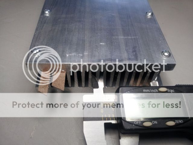
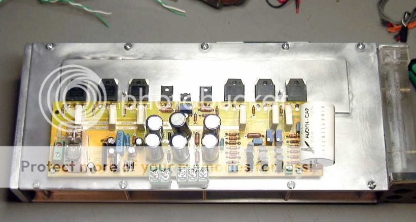
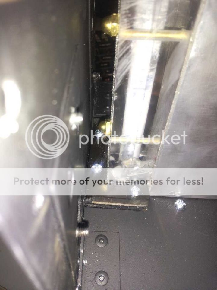
The thin web on these panels prompted me to add a blind strip to avoid drilling through and causing leaks. I used a permanent two part heat transfer adhesive. Mounting bolts are free but back taper heads insure proper tightness.
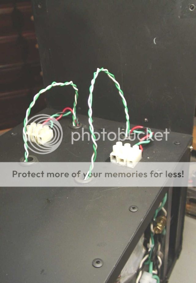
A little wire separating.
Pass through of amp floor.
Top and bottom bracket/flange joined with 6-32 screws.
Here is the first filler/drain cap plate (makes sense a bit later).
I/O RCAs and posts now installed. The yellow fuse is on the hot speaker lead and was added at the suggestion that the 500 VA transformer might be a little overpowering. Not sure if/how it could affect the signal quality.
Next Steps - Liquid Fill, Leak Test, Power Up
Rails are standard local hardware aluminum angle.
Switch, fan and mains inlet cut-outs.
Amp module floor riveted to intermediate rail supports. Added braces, cooler cut-out and rubber grommets for power leads.
Another scrap from an earlier project for the front.
*********************
These are the active components of the cooling system. There are several super quiet fans available from PC outlets. This and the Yate Loon are among the best.
Fan is attached to a 120mm radiator. I didn't use additional vibration insulating pads as the fan will run at a derated voltage and should be very quiet.
Radiator orientation has some effect on air pocket creation but a little twisting and rotating after final assembly moves them out.
Again, no gasket between radiator and chassis. Easy to add later if necessary.
I purchased a discrete speed controller but will most likely incorporate internal trimmers after cooling efficiency tests.
**********
For the reservoir Plexiglas again comes to the rescue. Any size/shape can be made and the medium threads almost as cleanly as metal.
The copper fitting is called a "stub rotating 90" and allows for easy adjustment of placement, angle and connecting tube length.
The plugs are modified standard fittings.
There is a diverter plate that enhances the potential for air bubbles to disperse to the top of the cooling fluid.
**********
Putting it all together!!!
With Honey Badger Clone
With F5 module.
The thin web on these panels prompted me to add a blind strip to avoid drilling through and causing leaks. I used a permanent two part heat transfer adhesive. Mounting bolts are free but back taper heads insure proper tightness.
A little wire separating.
Pass through of amp floor.
Top and bottom bracket/flange joined with 6-32 screws.
Here is the first filler/drain cap plate (makes sense a bit later).
I/O RCAs and posts now installed. The yellow fuse is on the hot speaker lead and was added at the suggestion that the 500 VA transformer might be a little overpowering. Not sure if/how it could affect the signal quality.
Next Steps - Liquid Fill, Leak Test, Power Up
we can fit kick butt ampz in a shoebox (amp itself), the power supplies save weight, genysys, especially the end result but aren't cheap. however no need to buy another, aleph 1000. Garden hose, cheap d6. I love this stuff!!
Rock on
Rock on
love the ingenuity and has geek factor for miles, but you'll excuse me for saying that it doesnt appear to be very shoebox sized, the F5 in particular I think could be made smaller passively. at the same time, i'm pretty sure you have more dissipation capacity than what is needed for an F5 or even F5 turbo? one note, isnt plexiglass a static risk?
photos are unnecessarily huge, I have 100MBit cable so no problem for me, but others may not be so impressed, there is no detail shown in the large pics that couldnt be shown smaller, you just havent resized them small enough from what was spat out from the camera.
photos are unnecessarily huge, I have 100MBit cable so no problem for me, but others may not be so impressed, there is no detail shown in the large pics that couldnt be shown smaller, you just havent resized them small enough from what was spat out from the camera.
Last edited:
A lesson from IBM's TCM Thermal Conduction Module water-cooled mainframes (now obsolete) was the use of dry-break quick-disconnects. I love them on fuel-injected motorcycles also. They seal both ends when you unhook them. With a big rack of amps, like for mobile PA, with a huge 3-phase high-voltage input power supply and a big centralized heat exchanger, you can make really small power amps with hoses and quick-disconnects on each for the coolant. Then you get some real packaging advantages, when you put a hundred amps into a rack, perhaps even separate racks for power and heat exchanger.
There's all kinds of brass disconnects made for hydraulics which seal both sides unlike the ones for pneumatics that just seal the air-supply side, but I really like the plastic high-pressure dry-break quick-disconnects that BMW uses on their K1200LT for the high-pressure fuel lines; I can take off the gas tank without leaking a drop. I know I got them cheaper from somewhere, probably Street & Competition Inc. Even some air disconnects seal both ends so you don't get a loud noise from the disconnected side draining down, but I don't know how they'd work for liquids.
There's all kinds of brass disconnects made for hydraulics which seal both sides unlike the ones for pneumatics that just seal the air-supply side, but I really like the plastic high-pressure dry-break quick-disconnects that BMW uses on their K1200LT for the high-pressure fuel lines; I can take off the gas tank without leaking a drop. I know I got them cheaper from somewhere, probably Street & Competition Inc. Even some air disconnects seal both ends so you don't get a loud noise from the disconnected side draining down, but I don't know how they'd work for liquids.
Last edited:
I think I'd favor construction which had a solid wall between the wet side and dry side in a stack of amps, and put the power and the heat exchanger into separate boxes. My livingroom has a rack of 10 power amps, and they could be three small boxes instead.
Nice way to do class-a also.
Wondeful to see your handiwork, and thank you for the pics.
Nice way to do class-a also.
Wondeful to see your handiwork, and thank you for the pics.
A TIG welder would also serve you well, but you need a pretty big one for welding aluminum because it conducts the heat away. Once it's assembled there's no need to open it, so welding the wet exchangers and the header would work great, also the preferred way to block off the end holes after drilling thru. I'm lucky and they guy next door is a true artisan with a big TIG in his garage, wonderful with aluminum and stainless etc.
- Status
- Not open for further replies.
- Home
- Amplifiers
- Chip Amps
- Liquid Cooling Build