Anyone know anything about the Linyun 300B integrated luxury edition amplifier? I'm looking for a decent, cheap entry level 300B amplifier. The Linyun caught my eye. It looks neat. No frills. One input, no selector switch. It just for some reason caught my eye, and I keep going back to it. They don't show the insides. So does anyone know anything about these amps? Thank you all.
"Luxury" indeed...
An externally hosted image should be here but it was not working when we last tested it.
Last edited:
Looks like it has many of the usual problems with this kind of amplifier:
- The big Alu-clad resistors - presumably the 300B auto-bias resistors - are designed to be chassis mounted, but instead are mounted on the PCB. With the usual 6-7W of power in each auto-bias resistor, these will get quite hot, and most of the heat will be conducted into the PCB. The nearest components to feel this heat are the high-quality electrolytic capacitors, which will have a short life running under such a heating. Up to 14W from the two resistors is no joke for a PCB or the caps.
Valve rectifier shared between two channels is likely to give bad bass and jumbled sound.
The filament supply is dc rectified with the cheap integrated bridge rectifiers. These drop enough voltage to get hot. They also have oversized recovery-time Trr, which is likely to give noise and buzz. 3-terminal voltage reg chips for the filament give assuredly bad sound.
Copy of tired old 6SN7 driver circuit is way behind what is possible for 300B drivers, and is unlikely to be well-implemented.
We can have no confidence that such incompetent design will produce good sound, and the reliability is certain to be annoyingly bad.
Rather than waste time on such a horror, which will be tough to upgrade, what with the PCB in the way, a scratch-build point to point amplifier would be far more rewarding, and provides much more learning opportunity, as you develop the sound.
There are some simple and easy to build versions of the « La maison de l'audiophile » 300B-SE around that can easily be implemented point-to-point, using a bit of tag-strip.
« Legacy » - Thorsten's version using the SV83 (= easy to buy Russsian 6П15П pentode) works very well:
Untitled Document
Rod,
That looks like a great design. I was working on a DIY design, for 300B, but keep having problems with it, and decided if I keep having problems with it, it probably won't be a very reliable amp in the long run. Anyway, I already have a pair of Electraprint 3.5K output transformers. I would like to use those if I build something. I put a lot of money into the failed project, so I only have about $1K left to put into an amp. If you know of a project amp out there that used 3.5K output tranny's please let me know. Also I would like something that was auto biasing if possible. Am I asking to much.
I was hoping to find a under $1K amp with good design, and good tranny's, that I could rebuilt at my leisure with all the High grade parts I have accumulated.
Any help would be highly appreciated. Thank You.
A pair of Electraprint 3.5K output transformers is a great start for any 300B-SE design. some published circuits say 2.4K OT on the drawing, because this value gives the highest output power. But you can go all the way to 5K with a 300B, and get slightly lower power - BUT - lower distortion and better sound. The Electraprints will be much higher quality than the made-to-a-price OTs on a generic (usually means incompetent) commercial amp.
I suggested the Legacy, since it has only one driver valve, making it easy to build - and better sounding than the usual 6SN7-cascade designs. You can use the 3.5K OTs on this design.
With these OTs, and $1K to spend, something nice is quite possible, if you are ready to do some wiring and assembly. But I am also assuming you're happy to work safely with 500V supplies - or to be able to call in some expert help before applying the power and testing for the first time.
You could also take one of the generic designs (like the one here) and try to fix the design faults. The 3.5K OT could also be used here, for better sound, but physical fit can be a problem in these cases. The first thing to do would be replace the auto-bias resistor - or shift it to the Alu chassis to dump the heat into the chassis instead of the PCB.
Have you had a look at the Tubelab SE, it seems like it would be a good fit for your goals. Lots have been built and there is plenty of help to be had over in the tubelab forum.
Details here: Tubelab SE | Tubelab
Details here: Tubelab SE | Tubelab
Have you had a look at the Tubelab SE, it seems like it would be a good fit for your goals. Lots have been built and there is plenty of help to be had over in the tubelab forum.
Details here: Tubelab SE | Tubelab
KevinKR,
That's the amp I keep having trouble with. I get it working for a while, then it craps out on me. I did use two brds and cut off part of each, to make a power supply brd, and an amp brd. Have them wired together with an umbilical. The power supply works great. The amp brd doesn't. It works great for a while when I get it to work. But then stops working. I haven't yet given up on it. But I don't have high hopes.
You really messed up the forum software with this goofball image! 😱"Luxury" indeed...

KevinKR,
That's the amp I keep having trouble with. I get it working for a while, then it craps out on me. I did use two brds and cut off part of each, to make a power supply brd, and an amp brd. Have them wired together with an umbilical. The power supply works great. The amp brd doesn't. It works great for a while when I get it to work. But then stops working. I haven't yet given up on it. But I don't have high hopes.
Try your best to describe how the amp "craps out" on you. There are many here who can provide advice as well.
For example - does it suddenly die? or over time get very quiet?
Also, try to explain what kind of speakers you use, what the sourse is and what your expectations are (i.e. do you like to listen to chamber music in a small room or metallica in a big room).
A pair of Electraprint 3.5K output transformers is a great start for any 300B-SE design. some published circuits say 2.4K OT on the drawing, because this value gives the highest output power. But you can go all the way to 5K with a 300B, and get slightly lower power - BUT - lower distortion and better sound. The Electraprints will be much higher quality than the made-to-a-price OTs on a generic (usually means incompetent) commercial amp.
I suggested the Legacy, since it has only one driver valve, making it easy to build - and better sounding than the usual 6SN7-cascade designs. You can use the 3.5K OTs on this design.
With these OTs, and $1K to spend, something nice is quite possible, if you are ready to do some wiring and assembly. But I am also assuming you're happy to work safely with 500V supplies - or to be able to call in some expert help before applying the power and testing for the first time.
You could also take one of the generic designs (like the one here) and try to fix the design faults. The 3.5K OT could also be used here, for better sound, but physical fit can be a problem in these cases. The first thing to do would be replace the auto-bias resistor - or shift it to the Alu chassis to dump the heat into the chassis instead of the PCB.
Rod,
That looks like a very doable design. I see it looks like I need A 1000 volt center taped power transformer. But he doesn't state how many milliamps?
Then there is a paragraph that confuses me. He states," All capacitors feature the complete recommended bypassing with 3600pf Euro KP1832, 2700pf NFS Styrofoam, and further 2200pf silver mica. Larger capacitors have further Euro KP1832 0.075 uf 800V bypass capacitor."
This paragraph is very confusing. I don't see any of these caps on the schematic, and I don't know what caps he talking about get the bypass caps, and it sounds like each capacitor gets all these bypass caps on each one?
Can you tell me the ma rating for the 1000 volt CT power tranny, and explain the capacitor paragraph, I would be very greatful, and I could start getting parts. Thank you very mush.
The thing is the tubelab design is generally very reliable and one of the best engineered designs out there. I'm a bit concerned as most of the designs out there are not in the same league quality wise, leaves me wondering what is going on. (Vague recollections from the tubelab thread)
its usually easier to fix what you already have - and tublab's design really should work.
Going over to these other designs will require different power supply requirements. I think Rod suggested the pentode driver one without knowing what you already had worked up and hand on hand...
Sometimes it is only a small simple thing. In a previous thread, a poster had tied both 300b heaters to the same power supply (for example).
its usually easier to fix what you already have - and tublab's design really should work.
Going over to these other designs will require different power supply requirements. I think Rod suggested the pentode driver one without knowing what you already had worked up and hand on hand...
Sometimes it is only a small simple thing. In a previous thread, a poster had tied both 300b heaters to the same power supply (for example).
Soulmerchant,
Heres what happened. The amp was working fine. Had been making music. Turned it on one day and the 5842's plate stared to glow red hot. Turned the amp off immediately. Was told on the forum it had to be the current regulator blew on that channel. I replaced the current regulators. Both of them. Powered up amp, and all checked out except I could only adjust the plate voltage on the 5842's to 160 volts. Put in power tubes and once B+ comes up I get a loud hum on both channels. I put together and cleaned another brd. This time with all my boutique resistors. Put new current regulators, and the new mosfet that Kevin recommended. This time the 5842 plate voltage adjusted to 175 volts. It was looking up. Put in the power tubes, and when B+ came up the same thing, a loud hum on both channels. I have two brds. I think I will take one with the standard parts, and strip it and put all new parts on it, and see if I can get it to work. But it seems like the mosfets are not working. The first time this happened I had about neg. 50 or 60 volts on the grid of the 300B, which I think would indicate that the mosfet was closed and the grid was getting no B+. I didn't measure the voltage on the grid of the 300B this last time, but I will, before I start disassembling the other brd. to rebuild.
If I still can't get it to work, well then I might try the Legacy amp. Except I'm worried I'll have to get the two power tranny's custom made. I'll let you know if it works out next try.
Hi Guarnera
Its this design right?

Can you try to post a picture of one of your boards? You need to go advanced and click "manage attachments", etc. on this forum.
Its this design right?
Can you try to post a picture of one of your boards? You need to go advanced and click "manage attachments", etc. on this forum.
Yes, I would usually support the idea of trying to fix the amp one already has.
I agree, also, that George's (Tubelab) work inspires confidence. As a radio designer, especially. But I hope that the posted schematic (above) is incomplete. The safety of the FET Q1 & Q2 require a gate-source zener: if the bias voltage appears before the B+ (i.e. the correct way around) the FET oxide will blow, since C9 will hold the gate while the source is pulled negative. Also, I can't imagine George omitting the gate-stopper resistor from a source follower - there will certainly be operating conditions (part of the swing waveform) where it will oscillate without one.
I agree, also, that George's (Tubelab) work inspires confidence. As a radio designer, especially. But I hope that the posted schematic (above) is incomplete. The safety of the FET Q1 & Q2 require a gate-source zener: if the bias voltage appears before the B+ (i.e. the correct way around) the FET oxide will blow, since C9 will hold the gate while the source is pulled negative. Also, I can't imagine George omitting the gate-stopper resistor from a source follower - there will certainly be operating conditions (part of the swing waveform) where it will oscillate without one.
I see it looks like I need A 1000 volt center taped power transformer. But he doesn't state how many milliamps?
Do you have ANY knowledge and experience to building tube amplifiers???
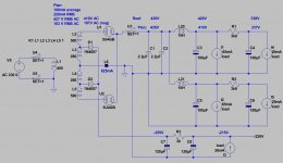
1000V CT (aka 500-0-500) good quality power transformer results at least 500V B+ (5AR4-CLC with "normal" 300B amp load -160..200mA-)!!!
This voltage and its transients would kill PSU capacitors, semiconductors, if PSU is not well designed!
I built several "powerdrived" 300B amps. This sample PSU is feed one of them.
Attachments
Hi Guarnera
Its this design right?
Can you try to post a picture of one of your boards? You need to go advanced and click "manage attachments", etc. on this forum.
Soulmerchant,
Yes that is it. Only thing not shown is there is now a 4.7K 1/4 watt resistor is between the volume pot and the grid of the 5842 tube at the input.
I see one problem that may be screwing things up. On the schematic it says B- should be about -150 volts. When I get it running with the 300B tubes in there I get about + 360 volts on my positive rail, which is fine. but my B neg. is always at about neg. 250V.
Here is what I have in the power supply. The full schematic is on the tubelab web sight. I'm and old dinosaur and don't know how to transfer it over to here. R5 is a 270 ohm 3 watt metal film Vishay resistor. It calls for 2 watt. I put in 5 different mills wire wound 5 watt resistors in this spot and they would blow as soon as I would power up. but a 2 watt metal film would work fine. C6 I have a 100uf mundorf tube cap. R6 is 10K and was upped to 6 watts. I have a Vishay 10K 10 watt wire wound resistor in this spot.C7 is another 100uf Mundorf tube cap. Then R7 is a 100K 2 watt resistor. Why is my B neg. so high, and could that be what keeps blowing things? Does the C6 value have to be lowered to bring my B- down? Please help. Thank you all very much.
- Status
- Not open for further replies.
- Home
- Amplifiers
- Tubes / Valves
- Linyun 300B Luxury edition