On main PCB I read this:
PCAS350/L2R 03-08-04 SERVO'D BASS BOARD PCB350L2
On sub board (part of SMPS-section) I read this:
PCAS350A/L2R DESIGN: DSW,AR,RS,ES
The following deficiencies I note at a visual inspection:
1) burned and damaged SMD resistor (maybe between 0R22 and 0R47) in series of the source from one of the four MOSFET's 20N6055 (primary area of SMPS)
2) 0R (i. e. shorting) between G-D-S of all this MOSFET's
3) overheating arround several electrolytics (e. g. C806, C809, C813, C105, C107)
Who can upload the schematic diagram of this module - particularly from the switch mode power supply section?
What are the main reason for the damaged MOSFET's ?
Thank you very much for helping.
Attachments
Last edited:
Interestingly I too am in the process of repairing one of these.
It came from a Sizmik 10.25, which does not use servo feedback, but is using the same PCB you describe.
In my case, Two switching MOSFETS are blown, the MOSFET driver IC, the PWM controller, a Diode under the transformer, a blown PCB track, and I think a small 3-pin SOT23 device labelled J1S9 that I have not yet been able to identify - either by googling, or reversing the schematic. It's part of the 110/230 v switching so I can bypass it if necessary.
And that's just on the Primary side of the PSU.
On the amplifier side, I've lost both Hybrids U401 and U501, and 3x 1w 3k3 resistors that appear to act as a minimum load for the PSU.
Note Nothing 'looks' burned on the amplifier side - except those 3x resistors which I think simply overheat due to poor heat-sinking.
Thankfully the rest of it powers up when run from a bench supply.
The burned SMT resistor you speak of is probably the 0.047 Ohms one near the two storage caps. It's about 3 x 10mm in size. Given it's low value I would be surprised if it had blown. But if all 4x of your MOSFETs are blown, it would have taken a direct mains short circuit.
If anyone could help identify a SOT23 device labelled J1S9, I would appreciate it!
Thanks
Paul
"S" looks similar than "5". Therefore probably 2SJ159.Interestingly I too am in the process of repairing one of these.
It came from a Sizmik 10.25, which does not use servo feedback, but is using the same PCB you describe.
In my case, Two switching MOSFETS are blown, the MOSFET driver IC, the PWM controller, a Diode under the transformer, a blown PCB track, and I think a small 3-pin SOT23 device labelled J1S9 that I have not yet been able to identify - either by googling, or reversing the schematic. It's part of the 110/230 v switching so I can bypass it if necessary.
And that's just on the Primary side of the PSU.
On the amplifier side, I've lost both Hybrids U401 and U501, and 3x 1w 3k3 resistors that appear to act as a minimum load for the PSU.
Note Nothing 'looks' burned on the amplifier side - except those 3x resistors which I think simply overheat due to poor heat-sinking.
Thankfully the rest of it powers up when run from a bench supply.
The burned SMT resistor you speak of is probably the 0.047 Ohms one near the two storage caps. It's about 3 x 10mm in size. Given it's low value I would be surprised if it had blown. But if all 4x of your MOSFETs are blown, it would have taken a direct mains short circuit.
If anyone could help identify a SOT23 device labelled J1S9, I would appreciate it!
Thanks
Paul
look here:
http://pages.na.industrial.panasonic.com/contact-us.html
for contact or call 800-344-2112 for asking datasheet.
"J1S9" isn't listed there:
https://www.sos.sk/pdf/SMD_Catalog.pdf
Thanks for your input,
Unfortunately 2SJ159 appears to be a TO220 device, not SOT23.
The mystery device is connected between the PSU 0v, the 5v reference from the PWM controller, and via a Diode, the sense voltage used to switch between 110 and 230v supply. The sense voltage is connected to a couple of voltage comparators (LM339) used to drive the relay - I still have to complete sketching out that section. I am assuming the device is faulty at the moment, because it is causing a ~2 Ohm short between 5v Ref and 0v.
An externally hosted image should be here but it was not working when we last tested it.
Thanks for your input,
Unfortunately 2SJ159 appears to be a TO220 device, not SOT23.
The mystery device is connected between the PSU 0v, the 5v reference from the PWM controller, and via a Diode, the sense voltage used to switch between 110 and 230v supply. The sense voltage is connected to a couple of voltage comparators (LM339) used to drive the relay - I still have to complete sketching out that section. I am assuming the device is faulty at the moment, because it is causing a ~2 Ohm short between 5v Ref and 0v.
An externally hosted image should be here but it was not working when we last tested it.
My image link does not appear to have worked, so let's try again:
Both possibilities are working at least on my own web access:
https://ibb.co/dNBtiQ
https_ibb.co/dNBtiQ (copy in the browser-addressfield and replace "_" by "://"
But upload of this file here on diyaudio is better.
Last edited:
If you right click and select 'open in new tab' then they often work but many users don't like externally hosted images because often there is other unwanted stuff on the server. Also after a period of time the images tend to disappear for various reasons related to the user and/or the account they are stored with.
Attaching directly to the forum is the preferred method every time.
Attaching directly to the forum is the preferred method every time.
Thank you for image attachment advice everyone... you can delete my previous posts!
Thanks for your input,
Unfortunately 2SJ159 appears to be a TO220 device, not SOT23.
The mystery device is connected between the PSU 0v, the 5v reference from the PWM controller, and via a Diode, the sense voltage used to switch between 110 and 230v supply. The sense voltage is connected to a couple of voltage comparators (LM339) used to drive the relay - I still have to complete sketching out that section. I am assuming the device is faulty at the moment, because it is causing a ~2 Ohm short between 5v Ref and 0v.
Attachments

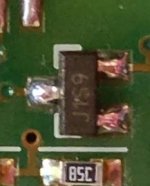
what means here J1S9 ?
5 Pcs BUZ91A 30V 60A N-channel Power MOSFET Transistors J1S9
https://picclick.co.uk/5-Pcs-BUZ91A-30V-60A-N-channel-Power-MOSFET-282336955095.html
according the attached image from the previouis posting the marking code is custom made for Linn - so I think.
5 Pcs BUZ91A 30V 60A N-channel Power MOSFET Transistors J1S9
https://picclick.co.uk/5-Pcs-BUZ91A-30V-60A-N-channel-Power-MOSFET-282336955095.html
according the attached image from the previouis posting the marking code is custom made for Linn - so I think.
Last edited:
Hi,
I think it's highly unlikely to be a custom marking when all the other devices are clearly manufacturer marked. I also think it would be impressive to fit a 60Amp device into a SOT23!
My money is on it being a Schottky dual diode with the same pinout as a BAV70. Schottkys fail like this, and the polarity would be correct to protect the 5v ref from reverse polarity transients, and limit the +supply sense net to the reference voltage as well. It is the inclusion of the other BAV70 has me confused... Perhaps they wanted a sturdier silicon diode junction in series as well for some reason.
I've emailed Linn for help, fingers crossed they reply.
Sent from my ONEPLUS A3003 using Tapatalk
Linn have been exceptionally helpful, and inform me that the mystery device is a Microprocessor reset IC:
Maxim MCP809T-475ITT
Interestingly neither the Maxim or now Microchip datasheet agree with the device markings, but this can happen when a company changes hands.
In circuit, it makes sense, it is holding the sense voltage at a fixed level whilst the PSU and reference voltage stabilise.
The circuit that drives the relay is a window comparator, the sense voltage must be above a minimum value, but obviously below a maximum value before the relay turns on. The thresholds change when the relay is switched.
The other diode package makes sure that the reset IC only interacts when it is in reset.
The micropower design of the reset IC means it can easily be powered by the Reference generator on the PWM controller.
I will replace the reset IC, but consider removing the relay, as I will never need to use this Amp at 115v.
Last edited:
LBL196
Hi. Sorry to reply on this old post. Please let me know if you were able to obtain the schematic for these boards? I have a power surge damaged Linn 10.25"active that I am hoping to get repaired.
On main PCB I read this:
PCAS350/L2R 03-08-04 SERVO'D BASS BOARD PCB350L2
On sub board (part of SMPS-section) I read this:
PCAS350A/L2R DESIGN: DSW,AR,RS,ES
The following deficiencies I note at a visual inspection:
1) burned and damaged SMD resistor (maybe between 0R22 and 0R47) in series of the source from one of the four MOSFET's 20N6055 (primary area of SMPS)
2) 0R (i. e. shorting) between G-D-S of all this MOSFET's
3) overheating arround several electrolytics (e. g. C806, C809, C813, C105, C107)
Who can upload the schematic diagram of this module - particularly from the switch mode power supply section?
What are the main reason for the damaged MOSFET's ?
Thank you very much for helping.
Hi. Sorry to reply on this old post. Please let me know if you were able to obtain the schematic for these boards? I have a power surge damaged Linn 10.25"active that I am hoping to get repaired.
Unfortunately not.Hi. Sorry to reply on this old post. Please let me know if you were able to obtain the schematic for these boards? I have a power surge damaged Linn 10.25"active that I am hoping to get repaired.
Because overheating in various PCB areas I don't recommend a repair service (only wasting time).
For more reliability a re-design of the Linn approach for it's module is necessary.
Search for the low pass filtre from post #5 under
Low pass filter for subwoofer.
(only available in used condition because out of production), and a good power amp like NAD etc.
An other possibility is the use of modules (plate versions) from the Dutch company Hypex - go to
Hypex Electronics B.V.
Last edited:
- Home
- Loudspeakers
- Subwoofers
- Linn Powered Subwoofer Model Akurate 226 - Schematic needed for LBL 196/3(A)