Hi,
I'm using a Linn LK100 (1995) with improved Capacitors on the power supply.
It performed great for a few years and now suddenly started going crazy.
After switching on, it plays great with power and oomph and all. Suddenly after a few minutes it dies out. No sound on Left or right speakers.
Dying out is pretty fast, but no 'click or pop' noise. Just as if someone had switched it off.
Switching it off (via the button) after it stopped playing has no effect, until about ~10-20 seconds after switching it off (pressing the On/Off button) - it suddenly plays for a few more seconds and then dies out.
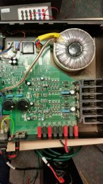
After measuring, I can say that the Toroid transformer receives the mains power and outputs two +33 VAC (Vs. common ground) voltage.
On the PCB it says '86V' next to it...
Any hint on what I should replace?
I would think that the capcitors on the AC-to-DC (power supply) part which seems to be common for both sides are not working OK.
Any other ideas or directions?
I'm using a Linn LK100 (1995) with improved Capacitors on the power supply.
It performed great for a few years and now suddenly started going crazy.
After switching on, it plays great with power and oomph and all. Suddenly after a few minutes it dies out. No sound on Left or right speakers.
Dying out is pretty fast, but no 'click or pop' noise. Just as if someone had switched it off.
Switching it off (via the button) after it stopped playing has no effect, until about ~10-20 seconds after switching it off (pressing the On/Off button) - it suddenly plays for a few more seconds and then dies out.
After measuring, I can say that the Toroid transformer receives the mains power and outputs two +33 VAC (Vs. common ground) voltage.
On the PCB it says '86V' next to it...
Any hint on what I should replace?
I would think that the capcitors on the AC-to-DC (power supply) part which seems to be common for both sides are not working OK.
Any other ideas or directions?
What you describe could be something as simple as a loose wire in the mains plug or a loose fuse (plug or amp).
It could also be a faulty mains switch.
For starters you need to connect you meter semi permanently across the pos and neg rails and see what happens when the amp goes off. A 33-0-33 transformer will give around 90 volts or slightly more DC voltage between the rails.
It could also be a faulty mains switch.
For starters you need to connect you meter semi permanently across the pos and neg rails and see what happens when the amp goes off. A 33-0-33 transformer will give around 90 volts or slightly more DC voltage between the rails.
HI,
Thanks for your help. Appreciated.
I measured the VAC read out on P402 (1st_brown-to-white and 2nd_brown-to-white):
With main (ON/OFF) switch on [but amp is in failure mode, i.e. not playing]--> 33-0-33
With main (ON/OFF switch off - 0-0-0.
So I guess the VAC reaches that point OK, even though the amp fails to amplify.
Where should I try and measure 90V ? Is that DC ?
Appreciated !
![url]](/community/proxy.php?image=http%3A%2F%2F%5Burl%3Dhttps%3A%2F%2Fimgbb.com%2F%5Durl+for+an+image%5B%2Furl%5D&hash=009a1cb2f9b772a8ed4511ffce10475a)
Thanks for your help. Appreciated.
I measured the VAC read out on P402 (1st_brown-to-white and 2nd_brown-to-white):
With main (ON/OFF) switch on [but amp is in failure mode, i.e. not playing]--> 33-0-33
With main (ON/OFF switch off - 0-0-0.
So I guess the VAC reaches that point OK, even though the amp fails to amplify.
Where should I try and measure 90V ? Is that DC ?
Appreciated !
Yes, DC although if the 33-0-33 AC is present in fault mode then its highly unlikely for the DC to be missing. The sound fading fast sounds for all the world like the supply disappearing.
The DC voltage is the addition of the DC voltage across each of the large reservoir caps and this voltage will be present on the output transistors (either emitter or collector depending on circuit configuration).
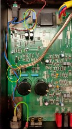
It would definitely help to see a circuit diagram for this, all I have are pictures of the internals. Other checks would be for DC offset on each output when the fault appears although tbh I can not see in the pictures any kind of speaker relay etc to mute the audio in the event of a fault.
I think there appears to be some discrete power supply circuitry at the front of the board... worth checking if anything is disappearing there.
As ever though... circuit diagram needed to advise in greater detail 🙂
The DC voltage is the addition of the DC voltage across each of the large reservoir caps and this voltage will be present on the output transistors (either emitter or collector depending on circuit configuration).
It would definitely help to see a circuit diagram for this, all I have are pictures of the internals. Other checks would be for DC offset on each output when the fault appears although tbh I can not see in the pictures any kind of speaker relay etc to mute the audio in the event of a fault.
I think there appears to be some discrete power supply circuitry at the front of the board... worth checking if anything is disappearing there.
As ever though... circuit diagram needed to advise in greater detail 🙂
Pictures. All I see is this.
Try attaching directly to the forum:
How to attach images to your posts.
Try attaching directly to the forum:
How to attach images to your posts.
Attachments

I'll look in later...
Is that a green LED I see on the board ? D403. Does that go out when the fault occurs ? It will probably be used as a voltage reference. Its just a clue as to things disappearing.
Is that a green LED I see on the board ? D403. Does that go out when the fault occurs ? It will probably be used as a voltage reference. Its just a clue as to things disappearing.
The LED stays on even when no sound is output.
It stays on even after I switch the unit for quite a substantial time.
It stays on even after I switch the unit for quite a substantial time.
open your amp,take out the circuit board and check all the welds.
the lk100 is a simply built amp, you should find quickly
the lk100 is a simply built amp, you should find quickly
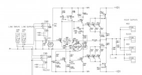
That gives you something to go on. The extra power supply components I mentioned aren't shown, however looking at the diagram it seems reasonable at this stage to suggest they probably provide the clean -/+30 volt rails.
So checking the DC voltages under fault conditions has to be the next step. Be sure to check the two 30 volt supplies. Also just for interest, when the fault does occur confirm that the DC offset remains close to zero. That is measured on either end of R217, it doesn't matter which.
So checking the DC voltages under fault conditions has to be the next step. Be sure to check the two 30 volt supplies. Also just for interest, when the fault does occur confirm that the DC offset remains close to zero. That is measured on either end of R217, it doesn't matter which.
Thanks.
So, for DC offset, I can test R217 (either end) against the GND. Correct?
Where should I test for -/+30 VDC? Could you point it out on the sent images ?
So, for DC offset, I can test R217 (either end) against the GND. Correct?
Where should I test for -/+30 VDC? Could you point it out on the sent images ?
Yes, and there should always be close to zero volts DC there, say -/+50mv or lower.
If voltage were present then your speakers would object... and if that were happening and there was a large offset then you would know to.
The plus 30 volts should be on the end of D203, the end without the black stripe.
The negative 30 volts can be picked up on the striped end of D205 or D208. Be careful notto slip with the meter probes and short anything out accidently.
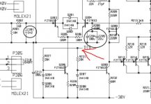
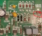
I'm just looking closely at the circuit to see what is or could be common to both channels and I spotted this......
The line marked DIS will be a bias voltage of some kind, possibly a delayed voltage to minimise switch on thumps and so on. I'm wondering if this voltage is disappearing for some reason. It seems to be shared between the channels, and if it goes missing I suspect it would cause your symptoms. The expected value could be anywhere from around minus 20 all the way to plus 40. Anything in that region will work as a bias voltage. If it falls to nearer minus 30 then the those two transistors Q206 and Q209 will be cut off and the amp will go quiet. That's the theory anyway 😉
Firstly, make sure the 3 pins are soldered properly. Look at them with a bright light and magnifying glass. There should be no trace of the solder cracking. In any event, having done that and if you are confident then I would resolder those points.
Also, if you can get the amp to misbehave then it would be worth comparing the voltages on the print going to those pins in both faulty and non faulty states before resoldering or even touching those pins. And be careful. Don't short anything.
Attachments
I spot a lot of horrible dipped tants in this thing. I'll lay good odds one of them is failing and causing issues.
Hello,
I dig up this post because I need help for my amp.
I recently bought a LK100 for a good price with no listening possible. Once at home I opened the box and discovered filter cards inside.
The cards were welded directly to different electronic components then I suppose the batch number is the oldest version of LK100 production.
I removed all the cards, replace one small resistor and took the opportunity to change all the caps at the same time.
All was done properly with good audio caps.
But now I got a "buzzzz" in my speakers with a level too high to be acceptable.
Linn can't help me. They just say that they've no longer spare parts for this amp.
It's a pity because it looks very good outside and also inside and I don't want to throw it away or cut parts out.
Someone has a idea where this buzzzz come from...?
Thanks a lot for help.
Alex
...from Belgium
- Home
- Amplifiers
- Solid State
- Linn LK100 issue