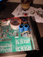
Thanks to everybody who tried to help. At the end of the day we have replaced the SPS with a normal toroidal transformer and now it is OK.
Cheers,
Ignat
Cheers,
Ignat
there is an advantage in all cases by using of SMPS, where an indoor power supply and transformer is in use near by the line/RIAA unit (in opposite to a classical 50 Hz transformer).So far I never understood why a low power line amp (or phono amp) would benefit from a SMPS.
But the use of a power supply in the same housing (i. e. near by the voltage amplifier stages) is generally considered by me to be very unfavorable, even by power amplifiers.
By an outdoor power supply I don't prefer SMPS by the currently available clock rates.
Nevertheless most brands don't prefer seperate outdoor power supplies (unfortunately).
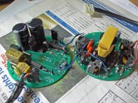
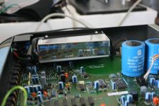
Great work. Unfortunately the showed device is the PCB of the line/phono preamplifier model "KAIRN" and not that one from LINTO. The still needed Schematic is that one of the SMPS device from LINTO.Looks like that at the moment. I will have to change a bit the housing - no problem. Replaced 14 electrolytic caps with 22 uf tantalum and opamps.
Cheers,
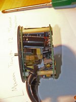
Here some additional pictures of the first picture from there, found about Linn Brilliant SMPS - naked! - pink fish mediaThe first picture shows the embedded SMPS, from which is the created schematic.
The second picture shows an other (older?) "Brilliant"- version from Linn. This schematic I don't have !!
(except the last pic - from this version I need also a schematic diagram).
Attachments
Last edited:
Thanks for the comment. In my case I do not have a RIAA stage but I am considering to take it out - I don't like the present arrangement. Will be easy to make a separate housing next to the preamp. Not an easy job with my three LK 100's but the most difficult is to take the decision - afterwords just copy-paste.there is an advantage in all cases by using of SMPS, where an indoor power supply and transformer is in use near by the line/RIAA unit (in opposite to a classical 50 Hz transformer).
But the use of a power supply in the same housing (i. e. near by the voltage amplifier stages) is generally considered by me to be very unfavorable, even by power amplifiers.
By an outdoor power supply I don't prefer SMPS by the currently available clock rates.
Nevertheless most brands don't prefer seperate outdoor power supplies (unfortunately).
Cheers,
Just a matter of curiosity - and my transistor circuit theory is rather rusty:
Perhaps one of you learned folk can answer the following.
If I look at the input circuit of the Linto signal circuitry (attached to the first post of this thread), I am puzzed. The very first signal transistor - when the audio comes from the moving coil cartridge does not appear to have a built in DC bias. The base is effectively floating being isolated from the outside world by a couple of capacitors.
How can this be? I thought stable transistor circuitry required a stable bias??
Sorry for what might me a dumb question to some of you...
don
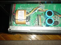
Hi, you can try using an R-core transformer instead - I have changed the toroid in the KAIRN for this one.schematic for "LINTO" SMPS still needed
Regards
yes, like used in the first editions of that models.Hi, you can try using an R-core transformer instead - I have changed the toroid in the KAIRN for this one.
Regards
I am still looking for the schematic of the SMPS from the Linto.
Definitively it is a right step ahead IMHO. Will post here the whole story of my mod I am very cslose to finalize-long story At the moment it is singing like a bird.🙂Is it possible by replacing the switchmode power supple with a transformer?
Cheers
No. You need additional a rectifier bridge or four pieces of high speed diodes, capacitors and voltage regulator, both for positive and negative voltage rail. Instead a serial regulator I would prefer a parallel regulator. And instead one supply for both channels I would prefer two monaural power supplies to optimize the GND management.Is it possible by replacing the switchmode power supple with a transformer?
schematic for "LINTO" SMPS still needed
no one here who has now opened this module and drawn the schematic diagram?
Last edited:
No. You need additional a rectifier bridge or four pieces of high speed diodes, capacitors and voltage regulator, both for positive and negative voltage rail. Instead a serial regulator I would prefer a parallel regulator. And instead one supply for both channels I would prefer two monaural power supplies to optimize the GND management.
no one here who has now opened this module and drawn the schematic diagram?
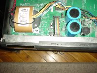
Fully agree but I have just replaced the diodes with hyper fast ones paralleled with 0.1 uF and simply delivered the required voltage by an R-core trafo - works fine so far.
Hi,
Thanks for all the info posted here. Our unit was tripping power light then dead. fault caused in our case by C19 on the AVS PWB.
Thanks
Thanks for all the info posted here. Our unit was tripping power light then dead. fault caused in our case by C19 on the AVS PWB.
Thanks
hi Niamex,
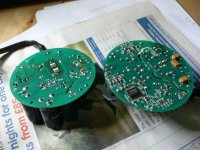
my Kairn SMP is also broken, could you please tell me the transformer each pin output voltage? so I can find a fitted a normal toroidal transformer. thanks.
my Kairn SMP is also broken, could you please tell me the transformer each pin output voltage? so I can find a fitted a normal toroidal transformer. thanks.
I need the schematic diagram from the switch mode power supply. Who can help?
From the experiment I have just done, you should build an analogue (regulated) PS which supplies the same DC voltage as the Linto SMPS does ... it will sound better! 🙂
(A SMPS is used for cost & size reasons - not SQ!)
Regards,
Andy
Last edited:
hi Niamex,
my Kairn SMP is also broken, could you please tell me the transformer each pin output voltage? so I can find a fitted a normal toroidal transformer. thanks.
Sorry I am late, it was long time ago and I do not remember exactly the voltages but you can see the photos and judge what to do - definitely new hyper fast soft recovering diodes /Fairchild/ and an R-core trafo.
Regards,
Ignat
Attachments
- Home
- Source & Line
- Analogue Source
- Linn "LINTO" MC Preamp Schematic without SMPS - Schematic for SMPS wanted