Has anyone had any success with a Linkwitz Transform? What set up are you running with? Any schematics?
I spent this afternoon playing with a rudimentary LT, and I found that it sends my amp into protection mode pretty quick also I got some ocillation. except for that I think the concept is good. I just need to tweak it .
I spent this afternoon playing with a rudimentary LT, and I found that it sends my amp into protection mode pretty quick also I got some ocillation. except for that I think the concept is good. I just need to tweak it .
re Linkwitz Transform
Jeff Macaulay publshed a design for a sub using a LT, and he said that it is very sensitive to component variations., especially with Q.
In the same way that state variable filters are less sensitive to component variations than Sallen - Key filters, I have a circuit that does the same thing as the LT, but is configured like a state variable filter. It uses a couple of integrators with feedback around them to perform the same function.
This was another project I never got round to; using a LT type boost and comparing it to MFB.
The circuit is from a paper published by the Audio Engineering Society, so it should be good. I'll see if I can dig it out.
ESP project 71 - Circuit and PC board at http://sound.westhost.com/project71.htm
A useful spreadsheet at:
http://www.pvconsultants.com/audio/eq/linktran.htm
A useful spreadsheet at:
http://www.pvconsultants.com/audio/eq/linktran.htm
I'd be interested in seeing that paper, johnnyx. Are you aware of Jeff Macaulay's second sub project in Electronics World where he used some kind of state-variable filter to perform the same function as a Linkwitz Transform? I wonder if this circuit is the same as what you have.
Might be worth buying the circuit board, as the circuit will be more fully developed and debugged. The results will be more deterministic. I have not seen anyone mention oscillation concerns with the PC board.
If you buy via credit card and let the card do the conversion the price will likely be better than the PayPal price.
If you buy via credit card and let the card do the conversion the price will likely be better than the PayPal price.
I built the circuit on a bread board from school, using "close values" that I had on hand. It was actually my first venture with active equilization and crossovers. I really don't know if it was osscilating, just that some unpleasent noises came out, and it drove the amp to cut after about 30 seconds. hum started low then got louder untill the amp went into shut down.
I appreciate the advice , but I will try again this week with more accurate parts, and a more carefull aproach to assyembly. I'm sure that I made a mistake somewhere.
I appoligize for posting this query twice, I really didn't know how many people view both forums.
I appreciate the advice , but I will try again this week with more accurate parts, and a more carefull aproach to assyembly. I'm sure that I made a mistake somewhere.
I appoligize for posting this query twice, I really didn't know how many people view both forums.
richie00boy said:Are you aware of Jeff Macaulay's second sub project in Electronics World where he used some kind of state-variable filter to perform the same function as a Linkwitz Transform? I wonder if this circuit is the same as what you have.
I've seen his circuit, it made me want to try it out. His method is different to the one I have, but I cann't remember the details. the one I have was published by the JAES, and it's ..somewhere..

Has anyone tried cheating a driver into working in a horn or TL by changing the Q with a LT circuit?
Linkwitz Transform
I used the ESP linkwitz transform and power supply boards. Both work great. There are 2 different spreadsheets for this circuit. They appear to be the same, but some components are labeled differently, and can cause you problems if you're not careful.
I used the ESP linkwitz transform and power supply boards. Both work great. There are 2 different spreadsheets for this circuit. They appear to be the same, but some components are labeled differently, and can cause you problems if you're not careful.
An externally hosted image should be here but it was not working when we last tested it.
Hi Aunkst!
I think you may have to issues.
1. oscilation and hum:
This has typically its origin in your filter circuitries.
You should measure the frequency response of your filter
and signal shape (ringing/ hum ??) of the filter circuit without
power amp first. Only if this signal is clear (no hum, no ringing)
and has the right frequency response, then it makes sense to
connect the hole system. Misfunction can easily drive the power amp to protection or may cause defects in your speakers!
2. Generally the linkwitz transform for improved bass gives high
gains at low frequencies. This will run the amp at higher power levels
than without linkwitz transform.
Hi Angel!
I did not try to change the Q with a linkwitz transform, but
with a negative output impedance of the amp!
Nice thing, for low frequencies you can imitate any driver Q.
If you look at the speaker itself there is a mechanical Q and an
electrical Q. The elctrical Q is a result of the magentic field , turns of bobbin, and coil resistance. The electrical loop is closed through the
amp. The output impedance of the amp is considered to be about zero, as it is typically much much less then the coil resistance.
So the resistance of the electrical loop is normaly the resistance of the loop.
If you increase the resistance of this loop the Q will increase, too.
Simply put a series resistance (and increase gain of amp in order to get the original signal level to the speake)
By lowering the resistance of the loop you can get lower Q.
For this your amp would need a negative output impedance.
For low frequencies you can achieve this by measuring the
current through the speaker and feed this signal back (positively!) to the input of the power amp..
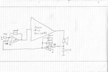
The attached schematic will make an -0.9 Ohm impedance.
1 A current through the current shunt will give a 0.1V to the inverting amp A2. Output of A2 will also be 0.1V.
A1 sums the current signal with the input.....
0.1V of the current signal + input will be given to the power amp.
The 0.1V of the current signal will result in 1V more out, due to the gain of 10 of the power amp.
This means 1A current through the speaker will make 1V MORE output, which means a negative output impedance of abpout -1 Ohm, well - 1 Ohm + 0.1 of the current shunt = -0.9 Ohm.
You can play around with various opamp circuits and you can simplify it down to 1 OP amp or no additional OP amp if you integrate all this into the feedback of the power amp.
But for first steps I would go this way, without modifying the power amp.
You have to take care for the following points:
-Check the gain and phase (inverting/ non inverting) of your
power amp!!! If your amp is inverting then you must use A2 in a noninverting connection.
- This current feedback is only suitful for low frequencies.
15nf in parallel to 10k cut off it effect above 1kHz. If you skip
the 15nF you can expect oscillations.
General this feedback may cause issues if your amp is critical
in frequency compensation.
-Value of negative output impedance must always be less than the
coil impedance!!!! Otherwise the circuit get instable as the
the loop (resistance of coil+ resistance of speaker)
is regulated to a negative overall resistance!!!!
-You may readjust the overall gain with the input resistor.
-Be careful and forget this idea if you are not familiar with
designing OP amp circuits, feedbacks, and frequency compensation.
Malfunction can cause defects in the power amp as well as in the speaker.
Good luck
Markus
I think you may have to issues.
1. oscilation and hum:
This has typically its origin in your filter circuitries.
You should measure the frequency response of your filter
and signal shape (ringing/ hum ??) of the filter circuit without
power amp first. Only if this signal is clear (no hum, no ringing)
and has the right frequency response, then it makes sense to
connect the hole system. Misfunction can easily drive the power amp to protection or may cause defects in your speakers!
2. Generally the linkwitz transform for improved bass gives high
gains at low frequencies. This will run the amp at higher power levels
than without linkwitz transform.
Hi Angel!
I did not try to change the Q with a linkwitz transform, but
with a negative output impedance of the amp!
Nice thing, for low frequencies you can imitate any driver Q.
If you look at the speaker itself there is a mechanical Q and an
electrical Q. The elctrical Q is a result of the magentic field , turns of bobbin, and coil resistance. The electrical loop is closed through the
amp. The output impedance of the amp is considered to be about zero, as it is typically much much less then the coil resistance.
So the resistance of the electrical loop is normaly the resistance of the loop.
If you increase the resistance of this loop the Q will increase, too.
Simply put a series resistance (and increase gain of amp in order to get the original signal level to the speake)
By lowering the resistance of the loop you can get lower Q.
For this your amp would need a negative output impedance.
For low frequencies you can achieve this by measuring the
current through the speaker and feed this signal back (positively!) to the input of the power amp..
The attached schematic will make an -0.9 Ohm impedance.
1 A current through the current shunt will give a 0.1V to the inverting amp A2. Output of A2 will also be 0.1V.
A1 sums the current signal with the input.....
0.1V of the current signal + input will be given to the power amp.
The 0.1V of the current signal will result in 1V more out, due to the gain of 10 of the power amp.
This means 1A current through the speaker will make 1V MORE output, which means a negative output impedance of abpout -1 Ohm, well - 1 Ohm + 0.1 of the current shunt = -0.9 Ohm.
You can play around with various opamp circuits and you can simplify it down to 1 OP amp or no additional OP amp if you integrate all this into the feedback of the power amp.
But for first steps I would go this way, without modifying the power amp.
You have to take care for the following points:
-Check the gain and phase (inverting/ non inverting) of your
power amp!!! If your amp is inverting then you must use A2 in a noninverting connection.
- This current feedback is only suitful for low frequencies.
15nf in parallel to 10k cut off it effect above 1kHz. If you skip
the 15nF you can expect oscillations.
General this feedback may cause issues if your amp is critical
in frequency compensation.
-Value of negative output impedance must always be less than the
coil impedance!!!! Otherwise the circuit get instable as the
the loop (resistance of coil+ resistance of speaker)
is regulated to a negative overall resistance!!!!
-You may readjust the overall gain with the input resistor.
-Be careful and forget this idea if you are not familiar with
designing OP amp circuits, feedbacks, and frequency compensation.
Malfunction can cause defects in the power amp as well as in the speaker.
Good luck
Markus
Attachments
ChocoHolic,
Pretty intriguing, but what would you say are the advantages of the approach you describe?
Pretty intriguing, but what would you say are the advantages of the approach you describe?
Hi Electron!
...advantage....
You will only get an advantage if you need a driver
with lower Q...
If you are lucky with the Q of your driver and it works
fine in you set up, then there is simply no need for
such a thing.
My proposal was just triggered by Angle, who asked about
changing the Q.
@johnnyx:
...yes, I remember..... long ago....
I think a scandinavian guy (K. E. Stahl) come up with these
ACE circuits....
Thanks, ...getting curious about the "simple MFB woofer project" thread.....
- Status
- Not open for further replies.
- Home
- Amplifiers
- Solid State
- Linkwitz Transform Circuit Design?