Well, I guess the proof is if it sounds good! I actually am having that one made in an olimex prototype board. I had some other stuff to made and needed to fill up a eurocard, and this one was the one I picked to throw in.
I guess we will see in a couple of weeks! 😀
I guess we will see in a couple of weeks! 😀
David,
the layout looks nice!
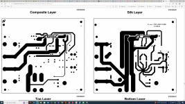
just 2 suggestion of double side pcb layout concept:
1,trying to isolated signal tracks and power supply tracks at different side,it can make all tracks short and clean.
2,set up the properties of polygon plate is remove dead copper.
Zang
the layout looks nice!
just 2 suggestion of double side pcb layout concept:
1,trying to isolated signal tracks and power supply tracks at different side,it can make all tracks short and clean.
2,set up the properties of polygon plate is remove dead copper.
Zang
David, isn't good to let all heavy devices ( PCB + elyts ) fit only by soldered pins of LM's... Remember also, that to PCB will be lead also heavy wires... Make there some fiting holes...
Absolutely! The problems I was running into was one of getting thick enough power traces without overlapping signal lines. I'll have to play with that a little and see if I can get everything in from the same side!digi01 said:1,trying to isolated signal tracks and power supply tracks at different side,it can make all tracks short and clean.
[edit] Oh, and the dead copper was supposed to act as shielding. I read somewhere (and I have no idea if it was credible) that as much copper coating the board as possible added to signal rejection. That may only have been if it was grounded, so I will try and find out if I am mis-remembering![/edit]
I completely agree about the devices being too heavy for just the chip pins. I can't believe I forgot to make mounting holes! As for the power, I was planning on using pinheaders and soldering power leads to those, but I think the direct wire method seems to have more suport, so from now on that will be what I will use for power.Upupa Epops said:David, isn't good to let all heavy devices ( PCB + elyts ) fit only by soldered pins of LM's... Remember also, that to PCB will be lead also heavy wires... Make there some fiting holes...
Thanks for the suggestions!

njhifi
take a look at the National lm4780 stereo amplifier artwork .Some pins are are NC(not connected ) but they are not connected internally and they are soldered on the board.
Do you have the boards to build the lm4780 pa03 amp?
Attachments
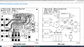
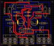
No doubt the data sheet is exactly as per what you have highlighted. Please check out the attached audiophile implementation of LM4780 and here the NC pins are connected. I wanted some info if there are any advantages in connecting these pins. As for the boards I have picked up a circuit from the net that supports 3 mode Stereo, Bridged and Parallel via few jumper settings using a 12 pin header. I am attaching the same. Have not ordered the PCB yet. For anyone interested in working on this design kindly note, I am not a professional PCB designer and hence mistakes are bound to be there and hence please do not use this design to build or order unless you are sure.
Attachments
- Home
- Amplifiers
- Chip Amps
- Linkwitz LM4780 PCB Proposal: Comments Wanted!