I understand that it won't prodce full power. I just wanted to know if the amp would be able to operate normally( just not full power) . Would there be any other draw backs?
Should I run radio at 1/4, 1/2 volume, when I test it ?
Should I run radio at 1/4, 1/2 volume, when I test it ?
I don't think the volume level is important. It's an old amp and could have other problems that may not show up unless it's on for a while. There are almost certainly a few electrolytics in the audio section that need to be replaced.
If you are not going to pay to have TIPS repair it and if you can't find another module, it may be possible to build a regulator circuit. It probably won't work precisely like the Linear module but it should regulate the rail voltage.
I'm not sure how much power the amp will deliver with the resistor in place. I've only used this (resistor subbed for transistor) for troubleshooting an amp with a defective module.
Tanks for the help. It was a good learning process for me.
Now I have to decide if I want to spend that much on this amp or not!
Now I have to decide if I want to spend that much on this amp or not!
After putting the module back in, to send amp off for repairs, it started working.
I am thinking that there could have been a cold solder joint on the module.
I see why you only used the resistor for testing purposes now. The rail voltage with the module is around 39v. With the resistor in place there is around 50v.
I am thinking that there could have been a cold solder joint on the module.
I see why you only used the resistor for testing purposes now. The rail voltage with the module is around 39v. With the resistor in place there is around 50v.
I found this old thread and was very helpful - I replaced q5 with the resistor, as suggested, and my 2502 is now working. Is there any way to find the schematic of the black box?
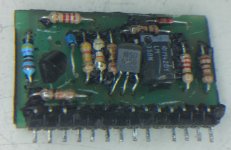
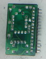
I got some pics of it I believe, but they are not high resolution. I remember seen a 2502IQ or it could of been a 2.2hv for sale recently on diyma that had that board exposed and it wasn't covered with epoxy either...really wanted to buy it just because of that lol.
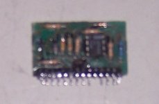
Yeah but the resolution on the pic posted is very bad., take some clear high resolution pics...both sides are needed. I use a 10x magnifier with LED to take close up pics with my cell camera, you'd be surprised on how clear they come out (cell camera is 5megapixel).
Last edited:
Yeah but the resolution on the pic posted is very bad., take some clear high resolution pics...both sides are needed. I use a 10x magnifier with LED to take close up pics with my cell camera, you'd be surprised on how clear they come out (cell camera is 5megapixel).
This is a good suggestion - I got a better camera and followed your instructions -
Attachments
- Status
- Not open for further replies.
- Home
- General Interest
- Car Audio
- LInear Power 2502IQ