For thoose, who don't know the antecedents:
It all started in SY's "A Heretical Unity gain line stage" thread, here:
http://www.diyaudio.com/forums/showthread.php?s=&threadid=58757&perpage=10&pagenumber=1
SY drew a line stage preamplifier, almos exactly what I was looking for.
I modified the schematic to what I exactly needed, and moamps advised, I should start a new thread, becouse of the modifications.
Regarding to my schematic, is that still wring?
(i will use a separate powersupply for the heating)
Why? I was always wondering about that ...
Isn't it enough, if I just feed with +24V DC the CCS ?
How do you mean that? Each one has a dedicated decoupling-capacitor?
Why? 🙂
I read about it in a paper, but that (the paper) was about switching mode powersupplies. That paper said, that the 90degree broke tracks act as a small antenna, and it is better using rounded trancks.
Is this (what you said) is about the same thing?
It all started in SY's "A Heretical Unity gain line stage" thread, here:
http://www.diyaudio.com/forums/showthread.php?s=&threadid=58757&perpage=10&pagenumber=1
SY drew a line stage preamplifier, almos exactly what I was looking for.
I modified the schematic to what I exactly needed, and moamps advised, I should start a new thread, becouse of the modifications.
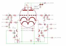
I have attached my "version" of the schematic.moamps said:Hi,
The drawing is better but maybe I should highlight a couple of things regarding SY's original schematic (not any variation thereof):
1) pin5 can't be connected to the ground,
Regarding to my schematic, is that still wring?
(i will use a separate powersupply for the heating)
2) CCS can't be connected to the ground but to -12V PS,
Why? I was always wondering about that ...
Isn't it enough, if I just feed with +24V DC the CCS ?
3) +B supplies should be separated.
How do you mean that? Each one has a dedicated decoupling-capacitor?
P.S. It is a common view that routing tracks under the right angle should be avoided.
Why? 🙂
I read about it in a paper, but that (the paper) was about switching mode powersupplies. That paper said, that the 90degree broke tracks act as a small antenna, and it is better using rounded trancks.
Is this (what you said) is about the same thing?
Attachments
Rounded/angled tracks are only required at very high frequencies. For audio use they are not a problem.
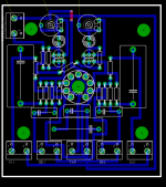
Could you put component names on the pcb? it makes tracing your work a lot easier! 🙂
Could you put component names on the pcb? it makes tracing your work a lot easier! 🙂
Thats fine, but where is, for instance, R52 on the pcb?
:edit: you beat me to it! 🙂
Interesting colour scheme, it could almost be one of those new disruptive camouflage patterns!
:edit: you beat me to it! 🙂
Interesting colour scheme, it could almost be one of those new disruptive camouflage patterns!
i use this strange solour scheme only for presentation.
It's easyer to read the values and in the same time the tracks are well visible.
It's easyer to read the values and in the same time the tracks are well visible.
It's OK.Danko said:Regarding to my schematic, is that still wring?
(i will use a separate powersupply for the heating)
Why? I was always wondering about that ...
Isn't it enough, if I just feed with +24V DC the CCS ?
If Va=100V and Ia=10mA, then Vgc=around -2V.
The CCS can't work correctly with only 2V on it.
How do you mean that? Each one has a dedicated decoupling-capacitor?
Each one has a dedicated RC network.
That paper said, that the 90degree broke tracks act as a small antenna, and it is better using rounded trancks.
Is this (what you said) is about the same thing?
Yes. It isn't the main issue here, though (that's why the remark is in P.S.).
But, if you don't have to use right angles, then don't.
Especially not in a "heretical" unity gain stage. 😉
Regards,
Milan
Hi moamps!
What happens if I don't separate the B+ supplies of the tube? The crosstalk will increase?
What R and C values do you recommend?
What happens if I don't separate the B+ supplies of the tube? The crosstalk will increase?
What R and C values do you recommend?
Danko said:What happens if I don't separate the B+ supplies of the tube? The crosstalk will increase?
What R and C values do you recommend?
Hi,
You're right, the crosstalk will increase.
See SY's schematic for R and C values.
Regards,
Milan
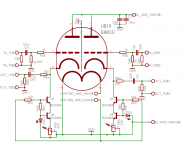
Is it a big problem, if I put the B+ filtering RC-network on another board, and not on the tube's board? In this case (when thr RC net. is not on that board) I put 1uF - 1uF capacitors to the B+.
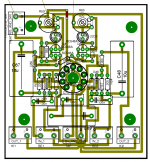
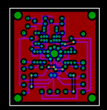
Is it a good idea, to create a biiiiiigbig plane on the component side, which is not connected to anywhere, except the GND, but the components aren't soldered to it? I'm thinking of somekind of shielding. Look ad the attached image!
The plane would be soldered to the central GND-star point with a wire.
There's another advantage this: I have ONLY 2-sided plain-PCB at home, and if I make single-sided boards, from one side of the board, the copper goes into trash. 🙂
Attachments
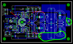
Preamp /almost/ finished!!
Hi all!
First of all, I would like to say thank you for everyone, who helped me in this project, especially to SY, who designed the circuit!! 🙂
And some technical stuff 🙂
I planned to use 100% switching mode powersupply for the tube, but the heating-supply wasn't good. I planned to use MAX8454, but it soooo small, I couldn't solder it 🙁
The plate supply was made with MAX1771 + IRF840. This boost-converter produces about 120VDC from 12V. After this, there come's a MOSFET stabilizer. This stabilizes the voltage to 108V. Of course, the mosfet doesn't just switch down instantly the plate voltage to the tube. The plate voltage slowly increases, in about 1 minute.
I miscalculated the summa voltage of the Zener-diodes, and since I soldered it, I haven't changed them... Is it a big problem, that the plate voltage is 108V instead of 90V ?
The heating is made with a 7805 + 2x1N4148. The diodes are connected series with the GND terminal of the 7805. When I first tested the heating supply, i have some doubt about how accuratly will be 6.3V the heating voltage, but I measured and it was 6.2X V, so I think it's OK.
This entire project is about a LINE STAGE amplifier, which is designed for a 10kOhm load impedance. But I tried to put my Sennheiser (HD202) headphones on this preamp. At my surprise, it sounded!! At maximum volume level the output voltage is about 600mV peak-to-peak. At this level the tube is distorting heavily.
Sy wrote, that the constant current generator must be set to 10mA. I put in series with the plates a 10 Ohm resistor, and I measured the current with this. Unfortunatelly I forget to buy 470 Ohm trim.pots, so I put instead of them 1kOhm trimpot. And /maybe becouse of this/ the minimum current, that I could set, was about 14mA. Isn't it too much?
Is it possible, to make some voltage amplification with this stuff? just a few deciBel -s, not 30dB 🙂
And once again, thank you for all, who helped me !!!
oh, by the way, i made a small A/B test with a relay.
I'm listening now with a Sennheiser HD202 headphone. And when I switch between the preamp, and between the PC (directly), I cannot hear so much difference.
Okay okay, i'm listening to mp3, but ....
I'm listening now with a Sennheiser HD202 headphone. And when I switch between the preamp, and between the PC (directly), I cannot hear so much difference.
Okay okay, i'm listening to mp3, but ....
With the adjustable CS, a higher resistance trimmer will result in lower current, not higher current. With a 1K pot turned to maximum, you should be able to get (1.7-0.7)/1K = 1mA of so. Are you sure you didn't slip a decimal place in your current measurement?
A 1K trimpot will still work, you'll just have to be working in the lowest part of its range.
A 1K trimpot will still work, you'll just have to be working in the lowest part of its range.
Thanks, tomorrow I will measure it again.
Now I just want to listen to this lil' thingie 🙂)
BTW, how can I amplify a few dB with this?
Now I just want to listen to this lil' thingie 🙂)
BTW, how can I amplify a few dB with this?
huh, i would like leave transformers out of this project 🙂
If it's too difficult (it can't be solved be simply changing one resistor), then i will use in this state, without amplification).
If it's too difficult (it can't be solved be simply changing one resistor), then i will use in this state, without amplification).
- Status
- Not open for further replies.
- Home
- Amplifiers
- Tubes / Valves
- Line stage preamp, based on SY's "Heretical Unity gain line stage"